Электропилы Bosch PTS 10 - инструкция пользователя по применению, эксплуатации и установке на русском языке. Мы надеемся, она поможет вам решить возникшие у вас вопросы при эксплуатации техники.
Если остались вопросы, задайте их в комментариях после инструкции.
"Загружаем инструкцию", означает, что нужно подождать пока файл загрузится и можно будет его читать онлайн. Некоторые инструкции очень большие и время их появления зависит от вашей скорости интернета.


English |
33
Bosch Power Tools
1 609 92A 039 | (28.9.12)
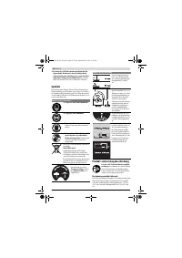
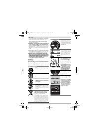
Use only saw blades that correspond with the characteristic
data given in these operation instructions and that are tested
and marked in accordance with EN 847-1.
Use only saw blades recommended by the tool manufacturer,
and suitable for sawing the materials to be cut.
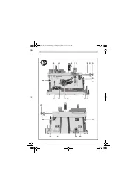
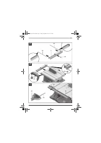
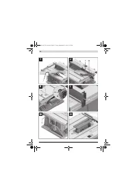
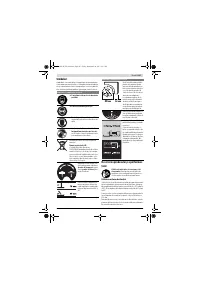
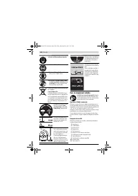
Removing the Saw Blade
– Using the ring spanner
17
, lift up the insert plate
3
at the
front and remove it from the notches
36
.
– Turn crank
12
clockwise to the stop, so that the saw blade
37
is in the highest possible position above the saw table.
– Turn the clamping nut
48
with the ring spanner
17
(23 mm) and at the same time, pull the spindle lock lever
47
until it engages.
– Keep the spindle lock lever pulled and unscrew the clamp-
ing nut turning in anticlockwise direction.
– Remove the clamping flange
49
.
– Remove the saw blade
37
.
Mounting the Saw Blade
If required, clean all parts to be mounted prior to assembly.
– Place the new saw blade onto the supporting flange
50
of
the tool spindle
51
.
Note:
Do not use saw blades that are too small. The clearance
between saw blade and riving knife must not exceed 5 mm
(max.).
When mounting the saw blade, pay attention that the
cutting direction of the teeth (arrow direction on the
saw blade) corresponds with the direction of the arrow
on the blade guard!
– Mount the clamping flange
49
and the clamping nut
48
.
– Turn the clamping nut
48
with the ring spanner
17
(23 mm) and at the same time, pull the spindle lock lever
47
until it engages.
– Tighten the clamping nut in clockwise direction.
– Reinsert the insert plate
3
. (see figure c3)
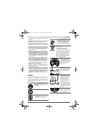
Operation
Before any work on the machine itself, pull the mains
plug.
Transport and Working Position of the Saw Blade
Transport Position
– Turn crank
12
in anticlockwise direction until the teeth of
the saw blade
37
are positioned below the saw table
11
.
Working Position
– Turn the crank
12
clockwise, until the teeth of the saw
blade
37
are positioned above the workpiece.
Note:
Take care that the blade guard is properly positioned.
When sawing, it must always face against the workpiece.
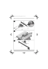
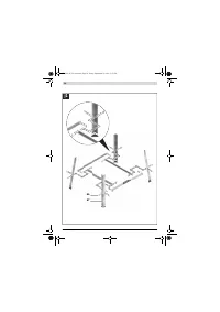
Increasing the Size of the Saw Table
Long workpieces must be underlaid or supported at their free
end.
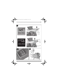
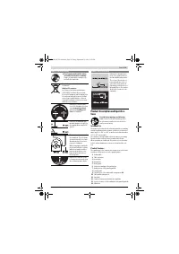
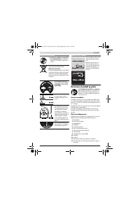
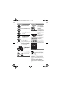
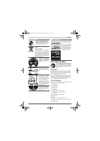
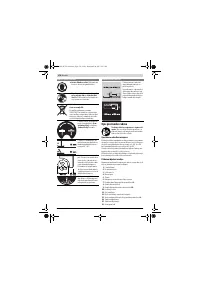
Table Extension/Table Width Enlargement (see figure A)
To increase the saw table surface, the following rails can be
pulled out at the rear as well as on the right-hand side of the
power tool:
Table extension 2
(extends the saw table
11
toward the rear
by 215 mm)
and/or
Table width enlargement 10
(enlarges the saw table
11
to-
ward the right by 285 mm)
– Grasp the requested rail centrally and from below, and pull
it out maximally to the stop.
– To lock in position, tighten the corresponding fastening
knobs (
23
or
26
) against the guide rods.
For heavy workpieces, it may be required to support the rails.
Sliding Table (see figure B)
With the sliding table
1
, workpieces to a maximum width of
350 mm can be sawn.
At the same time, a higher precision is achieved during saw-
ing, especially in conjunction with the angle stop
16
. (see
“Sawing Mitre Angles with the Sliding Table”, page 35)
– For this, tilt the locking lever
24
toward the right.
In this manner, the sliding table can be moved both toward
the front as well as toward the rear to the stop.
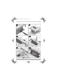
Adjusting the Cutting Angle
To ensure precise cuts, the basic adjustment of the machine
must be checked and adjusted as necessary after intensive
use (see “Checking and Adjusting the Basic Adjustment”,
page 35).
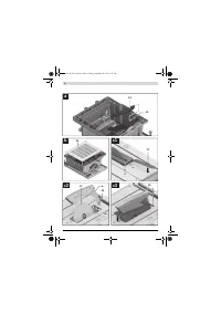
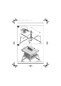
Adjusting Mitre Angles (Angle Stop) (see figure C)
The mitre angle can be set in the range from 60 ° (left side) to
60 ° (right side).
– Loosen the locking knob
52
in case it is tightened.
– Turn the angle stop until the angle indicator
53
indicates
the requested mitre angle.
– Tighten the locking knob
52
again.
Adjusting Bevel Angles (Saw Blade) (see figure D)
The bevel angle can be set in the range from 0 ° to 45 ° .
– Lightly unscrew the locking knob
29
in anticlockwise direc-
tion.
Note:
By completely loosening the locking knob, the saw
blade tilts approx. to the 30 ° position by means of gravity
force.
– Press handwheel
54
toward the rear and hold it in this po-
sition.
This forces the teeth on the connecting link to engage in
the gear ring of the handwheel.
– Turn the handwheel until the angle indicator
55
indicates
the requested bevel angle on the scale
56
.
– Tighten the locking knob
29
again.
For quick and precise setting of the standard angles 0 °
and 45 °
, end stops are given at the housing.
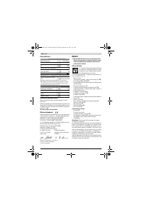
OBJ_BUCH-783-006.book Page 33 Friday, September 28, 2012 2:27 PM
Содержание
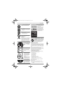
- 202 Применение электроинструмента и обращение с ним
- 203 Символы; Символы и их значение
- 204 Описание продукта и услуг; Применение по назначению
- 205 Технические данные; Применяйте средства защиты органов слуха!; Заявление о соответствии; Сборка; Комплект поставки; В исполнениях электроинструмента с подставкой; Размеры пильных дисков
- 206 Первое включение; Последовательность монтажа; Монтаж снизу
- 207 Отсос пыли и стружки; Избегайте скопления пыли на рабочем месте.; Стационарный или временный монтаж
- 208 Работа с инструментом; Увеличение площади стола
- 209 Настройка параллельных упоров
- 210 Максимальные размеры заготовки; Пиление; Выполнение прямых пропилов; Основные настройки – контроль и коррекция; Настройка угла наклона в 0 °
- 211 Хранение электроинструмента; Техобслуживание и сервис; Техобслуживание и очистка; Очистка; Принадлежности; Товарный No
- 212 Россия; Утилизация


