Электропилы Bosch PTS 10 - инструкция пользователя по применению, эксплуатации и установке на русском языке. Мы надеемся, она поможет вам решить возникшие у вас вопросы при эксплуатации техники.
Если остались вопросы, задайте их в комментариях после инструкции.
"Загружаем инструкцию", означает, что нужно подождать пока файл загрузится и можно будет его читать онлайн. Некоторые инструкции очень большие и время их появления зависит от вашей скорости интернета.


English |
31
Bosch Power Tools
1 609 92A 039 | (28.9.12)
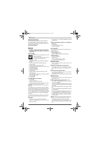
Assembly
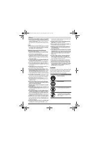
Avoid unintentional starting of the machine. During as-
sembly and for all work on the machine, the power plug
must not be connected to the mains supply.
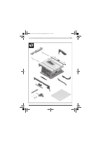
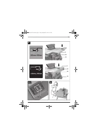
Delivery Scope
Please also observe the representation of the
delivery scope at the beginning of the operat-
ing instructions.
Before starting the operation of the machine
for the first time, check if all parts listed below
have been supplied:
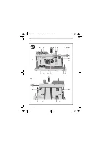
– Table saw
(Preassembled: Table width enlargement
10
, saw blade
37
, insert plate
3
)
– Bottom plate
34
with pre-mounted Phillips screws
– Table extension
2
– Fastening kit for “table extension”
39
(2 guide rods, 2 securing screws, 2 clips, 2 short fastening
knobs)
– Parallel fences
8
and
9
– Auxiliary stops
7
and
18
– Angle stop
16
– Fastening kit “for auxiliary stop/angle stop”
43
– Blade guard
5
,
Riving knife
4
with pre-mounted hexagon bolt
35
– Vacuum hose
33
– Push stick
22
– Ring spanner
17
for machine versions with base unit:
– Base unit
67
(12 Profiles, 4 end caps)
– Fastening kit for base unit
66
(24 screws with nuts for assembly, 4 screws with nuts for
fastening of the machine, 4 washers)
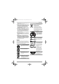
Note:
Check the power tool for possible damage.
Before further use of the machine, check that all protective
devices are fully functional. Any lightly damaged parts must
be carefully checked to ensure flawless operation of the tool.
All parts must be properly mounted and all conditions fulfilled
that ensure faultless operation.
Damaged protective devices and parts must be immediately
replaced by an authorised service centre.
Initial Operation
– Carefully remove all parts included in the delivery from
their packaging.
– Remove all packaging material from the machine and the
accessories provided.
– Take care that the packaging material under the motor
block es removed.
Additionally required tools (not in delivery scope):
– Phillips screwdriver
– Angle gauge
– Box-end or open-end spanner (size 13 mm)
for assembly of the base unit
Assembly Sequence
For easier working, observe the assembly sequence of the
supplied product features.
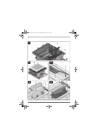
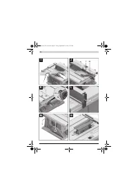
1. Assembly from Below
– Vacuum hose
33
– Bottom plate
34
with pre-mounted Phillips screws
2. Assembly from Above
– Riving knife
4
– Table extension
2
– Angle stop
16
and auxiliary stop
18
– Parallel guide
8
and auxiliary stop
7
Assembly from Below
– Turn the machine around so that it is upside down on the
saw table
11
.
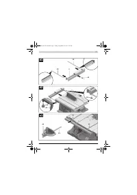
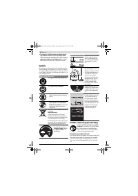
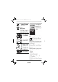
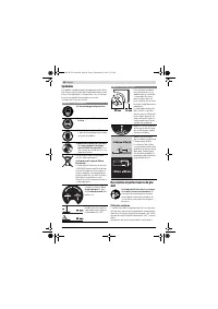
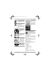
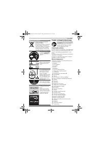
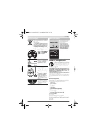
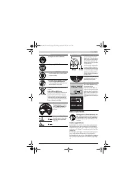
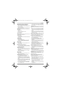
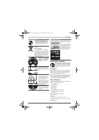
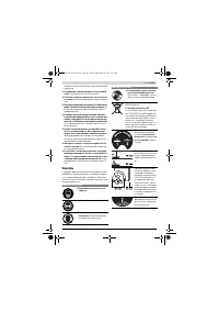
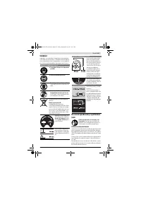
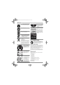
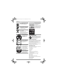
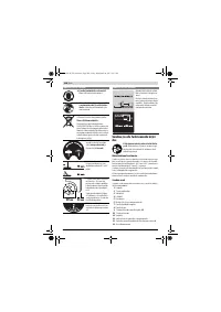
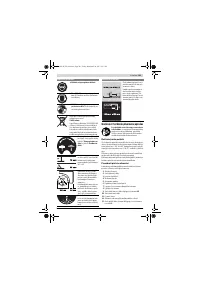
Mounting the Vacuum Hose (see figure a)
– Connect the sawdust ejector on the saw blade casing and
the sawdust ejector
31
on the machine housing with the
vacuum hose
33
.
Mounting the Bottom Plate (see figure b)
– Insert the bottom plate
34
into the intended recesses so
that the Phillips screws can be screwed into the holes of
the housing.
– Fasten the bottom plate by screwing in and tightening the
Phillips screws.
Assembly from Above
– Turn the power tool around so that it is in the correct work-
ing position.
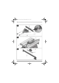
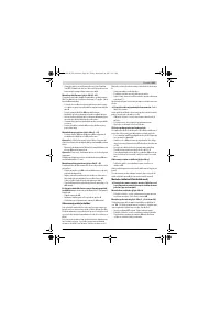
Mounting the Riving Knife (see figures c1
–
c3)
– Using the ring spanner
17
, lift up the insert plate
3
at the
front and remove it from the notches
36
.
– Turn crank
12
clockwise to the stop, so that the saw blade
37
is in the highest possible position above the saw table.
– Loosen locking knob
29
to tilt the saw blade
37
.
– Insert the riving knife
4
so that the respective holes are po-
sitioned on the guide bolts of the riving knife fixture
38
.
– Fasten the riving knife
4
to fixture
38
by firmly tightening
hexagon bolt
35
with ring spanner
17
(13 mm).
– Readjust the saw blade back to 90 ° again and tighten lock-
ing knob
29
. (also see “Adjusting Bevel Angles”, page 33)
Note:
The riving knife must be in alignment with the saw blade
to avoid jamming of the workpiece.
– Finally, reassemble the insert plate
3
.
For this, hook the insert plate into the notches
36
and then
press the insert plate downward until it engages in the saw
table.
– Tighten the nut of the blade guard sufficiently with the ring
spanner
17
(13 mm) so that the blade guard remains se-
cured in any set position.
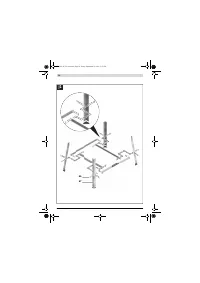
Mounting the Table Extension (see figures d1
–
d2)
For assembly, use the fastening kit for “table extension”
39
.
(2 guide rods, 2 securing screws, 2 clips, 2 short fastening
knobs)
OBJ_BUCH-783-006.book Page 31 Friday, September 28, 2012 2:27 PM
Содержание
- 202 Применение электроинструмента и обращение с ним
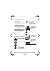
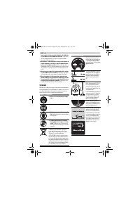
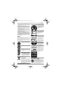
- 203 Символы; Символы и их значение
- 204 Описание продукта и услуг; Применение по назначению
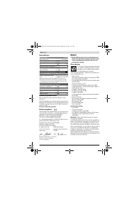
- 205 Технические данные; Применяйте средства защиты органов слуха!; Заявление о соответствии; Сборка; Комплект поставки; В исполнениях электроинструмента с подставкой; Размеры пильных дисков
- 206 Первое включение; Последовательность монтажа; Монтаж снизу
- 207 Отсос пыли и стружки; Избегайте скопления пыли на рабочем месте.; Стационарный или временный монтаж
- 208 Работа с инструментом; Увеличение площади стола
- 209 Настройка параллельных упоров
- 210 Максимальные размеры заготовки; Пиление; Выполнение прямых пропилов; Основные настройки – контроль и коррекция; Настройка угла наклона в 0 °
- 211 Хранение электроинструмента; Техобслуживание и сервис; Техобслуживание и очистка; Очистка; Принадлежности; Товарный No
- 212 Россия; Утилизация


