Пилы торцовочные Bosch GCM 800 SJ - инструкция пользователя по применению, эксплуатации и установке на русском языке. Мы надеемся, она поможет вам решить возникшие у вас вопросы при эксплуатации техники.
Если остались вопросы, задайте их в комментариях после инструкции.
"Загружаем инструкцию", означает, что нужно подождать пока файл загрузится и можно будет его читать онлайн. Некоторые инструкции очень большие и время их появления зависит от вашей скорости интернета.


English |
23
Bosch Power Tools
1 609 92A 3BW | (14.6.17)
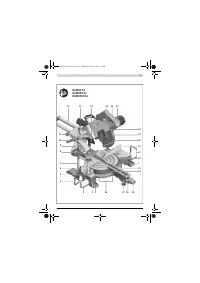
19
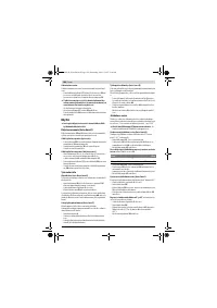
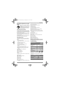
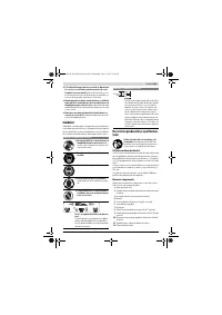
Retracting blade guard
20
Roller
21
Fence
22
Saw table
23
Insert plate
24
Mitre angle indicator
25
Locking knob for various mitre angles
26
Mitre detent lever
27
Tilt protector
28
Detents for standard mitre angles
29
Spindle lock
30
Transport safety-lock
31
Scale for bevel angle
32
Indicator for bevel angle
33
Stop screw for 0 ° bevel angle
34
Stop for 0 ° bevel angle
35
Hex key (size 5 mm)/cross-head screwdriver
36
Hex socket screw for mounting of saw blade
37
Clamping flange
38
Interior clamping flange
39
Saw blade
40
Locking screw of the adjustable fence
41
Mounting holes for material clamp
42
Threaded rod
43
Screws for insert plate
44
Screw for bevel angle indicator
45
Screw for mitre angle indicator
Accessories shown or described are not part of the standard deliv-
ery scope of the product. A complete overview of accessories can
be found in our accessories program.
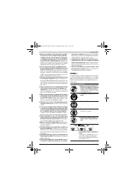
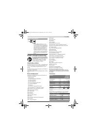
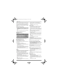
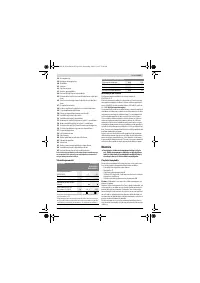
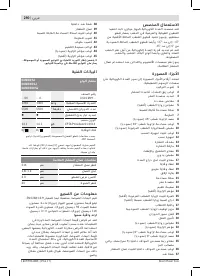
Technical Data
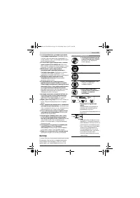
Noise Information
Sound emission values determined according to
EN 62841-3-9.
Typically the A-weighted noise levels of the product are:
Sound pressure level 93 dB(A); Sound power level
106 dB(A). Uncertainty K = 3 dB.
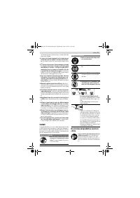
Wear hearing protection!
The noise emission value given in these instructions has been
measured in accordance with a standardised measuring pro-
cedure and may be used to compare power tools. It may also
be used for a preliminary estimation of noise emissions.
The noise emission value given represents the main applica-
tions of the power tool. However, if the power tool is used for
other applications, with different accessories or is poorly
maintained, the noise emission value may differ. This may sig-
nificantly increase noise emissions over the total working pe-
riod.
To estimate noise emissions accurately, the times when the
tool is switched off, or when it is running but not actually being
used, should also be taken into account. This may significant-
ly reduce noise emissions over the total working period.
Assembly
Avoid unintentional starting of the machine. During as-
sembly and for all work on the machine, the power plug
must not be connected to the mains supply.
Delivery Scope
Before starting the operation of the machine for the first time,
check if all parts listed below have been supplied:
– Sliding mitre saw with mounted saw blade
– Material clamp
7
– Saw-table extension
3
Clamping screw
2
x 2, cross-head screw x 2 to prevent the
saw table extensions from being pulled out of the saw table
– Hex key/cross-head screwdriver
35
Note:
Check the power tool for possible damage.
Before further use of the machine, check that all protective
devices are fully functional. Any lightly damaged parts must
be carefully checked to ensure flawless operation of the tool.
All parts must be properly mounted and all conditions fulfilled
that ensure faultless operation.
Damaged protective devices and parts must be immediately
replaced by an authorised service centre.
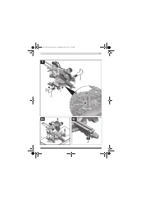
Mounting Saw-table Extensions (see figure A)
The saw table can be extended left and right with the saw-ta-
ble extensions
3
.
– Slide the saw table extensions in as far as they will go
through the holes provided in the saw table.
– Turn the power tool upside down so that you can screw in
the two cross-head screws provided to prevent the saw ta-
ble extensions from being pulled out of the saw table.
Screw the cross-head screws into the threaded holes pro-
vided in the saw table extensions
3
and use a cross-head
screwdriver
35
to tighten them.
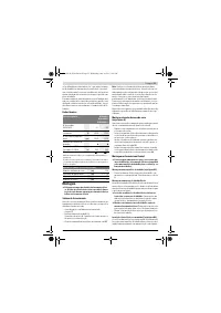
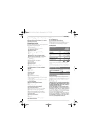
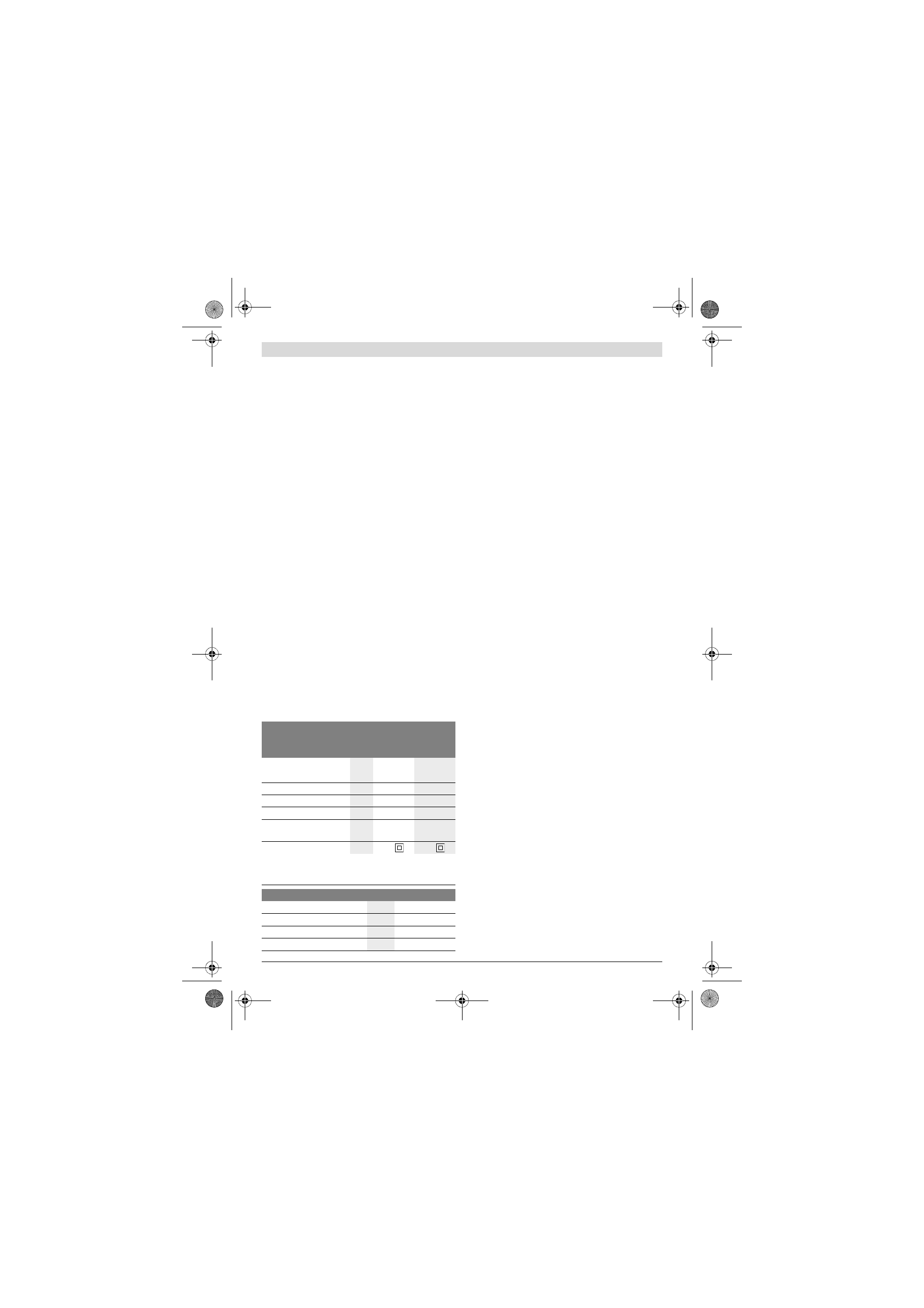
Sliding Mitre Saw
GCM 80 SJ
GCM 800 SJ
GCM 8000 SJ
Article number
3 601 M19 ...
... 0..
... 06.
Rated power input
W
1400
1250
No-load speed
min
-1
5500
5500
Reduced starting current
Weight according to EPTA-
Procedure 01:2014
kg
14.1
14.1
Protection class
/
II
/
II
Permissible workpiece dimensions (maximum/minimum) see page 26.
The values given are valid for a nominal voltage [U] of 230 V. For differ-
ent voltages and models for specific countries, these values can vary.
Dimension of suitable saw blades
Saw blade diameter
mm
216
Blade body thickness
mm
1.3 – 1.8
Max. cutting width
mm
3.3
Mounting hole diameter
mm
30
OBJ_BUCH-2154-004.book Page 23 Wednesday, June 14, 2017 5:06 PM
Содержание
- 170 Безопасность людей
- 171 Сервис
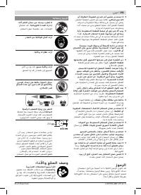
- 172 Держите Ваше рабочее место в чистоте.; Символы; Символы и их значение
- 173 Описание продукта и услуг; Применение по назначению; Технические данные; Панельная пила; Размеры пильных дисков
- 174 Данные о шуме; Применяйте средства защиты органов слуха!; Сборка; Комплект поставки; Монтаж на верстаке производства Bosch; Отсос пыли и стружки
- 175 Избегайте скопления пыли на рабочем месте.; Работа с инструментом
- 176 Подготовка к эксплуатации; Для быстрой и точной установки угла 0 ° и 45 °; Включение электроинструмента; включения
- 177 Указания по применению; Общие указания для пиления; Пиление; Резание с тяговым движением
- 178 Основные настройки – контроль и коррекция; Настройка угла наклона в 0 °; Техобслуживание и сервис; Техобслуживание и очистка; Очистка
- 179 Принадлежности; Россия; Утилизация; Товарный No; Пильные диски для пластмассы и цветных металлов
Характеристики

Остались вопросы?Не нашли свой ответ в руководстве или возникли другие проблемы? Задайте свой вопрос в форме ниже с подробным описанием вашей ситуации, чтобы другие люди и специалисты смогли дать на него ответ. Если вы знаете как решить проблему другого человека, пожалуйста, подскажите ему :)


