Кондиционеры Daikin EWAQ-GZXR - инструкция пользователя по применению, эксплуатации и установке на русском языке. Мы надеемся, она поможет вам решить возникшие у вас вопросы при эксплуатации техники.
Если остались вопросы, задайте их в комментариях после инструкции.
"Загружаем инструкцию", означает, что нужно подождать пока файл загрузится и можно будет его читать онлайн. Некоторые инструкции очень большие и время их появления зависит от вашей скорости интернета.


D-EIMAC01109-14EU - 13/208
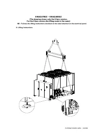
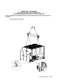
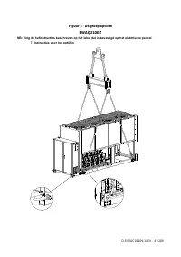
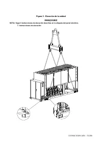
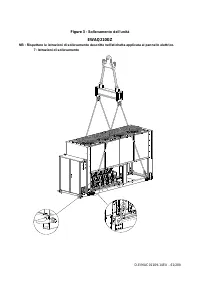
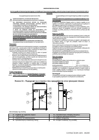
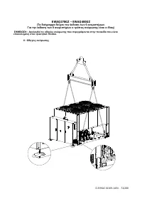
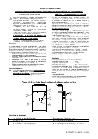
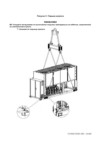
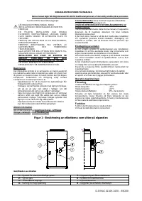
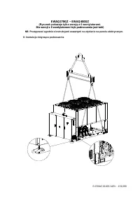
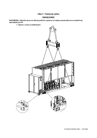
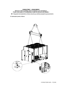
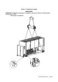
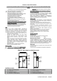
Rigging instruction
-
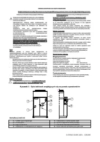
The lifting equipment, ropes/chains, accessoriesnand the
rigging procedure must be in conformity with local
regulations and current rules.
-
Only the lifting points,present in the base frame, must be
used to lift the unit. Lifting point are identified by yellow
colour. The number of fans can very from this diagram
depending on the size of the unit.
-
All lifting points must be used during rigging procedure.
-
Only closable hooks must beused during rigging
procedure.
-
Ropes/chains and hooks must be adequate for load. See
specific lifting weight of the unit on the identification label.
-
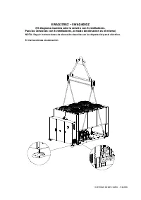
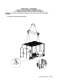
Crosswise spreader bars 1400 mm (EWAQ210GZ) and
2300 mm (EWAQ270GZ~EWAQ400GZ) long must be
used to avoid damage to the unit.
-
Lifting ropes/chain must have a minimum length as it is
specified in the drawing.
-
The installer has the responsibility for proper sizing of
rigging
-
Equipment and its proper use. It’s recommended to use
ropes/chains each with minimum vertical load capacity
equal or larger than unit weight.
-
The unit must be slowly lifted and properly leveled. Adjust
the rigging equipment, to guarentee the leveling.
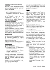
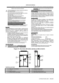
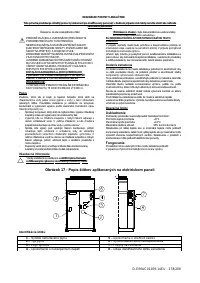
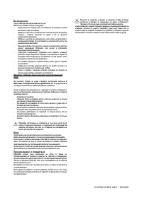
Positioning and assembly
All units are designed for installation outdoors, either on
balconies or on the ground, provided that the installation area
is free of obstacles that could reduce air flow to the
condensers coil.
The unit must be installed on a robust and perfectly level
foundation; should the unit be installed on balconies or roofs, it
might be necessary to use weight distribution beams.
For installation on the ground, a strong concrete base, at least
250 mm thickness and wider than the unit must be provided.
This base must be able to support the weight of the unit.
If the unit is installed in places that are easily accessible to
people and animals, it is advisable to install protection grids for
the condenser and compressor sections.
To ensure best performance on the installation site, the
following precautions and instructions must be followed:
-
Avoid air flow recirculation.
-
Make sure that there are no obstacles to hamper air
flow.
-
Make sure to provide a strong and solid foundation
to reduce noise and vibrations.
-
Avoid installation in particularly dusty environments,
in order to reduce soiling of condensers coils.
- The water in the system must be particularly clean and all
traces of oil and rust must be removed. A mechanical water
fil
ter must be installed on the unit’s inlet piping.
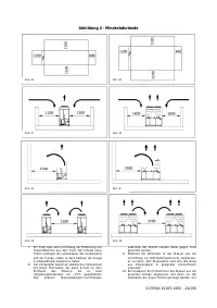
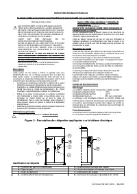
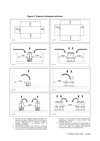
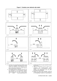
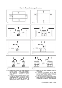
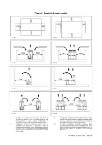
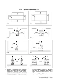
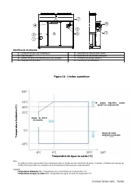
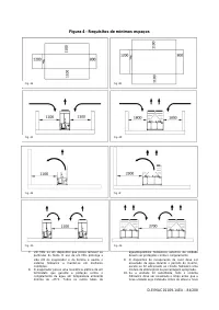
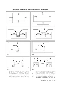
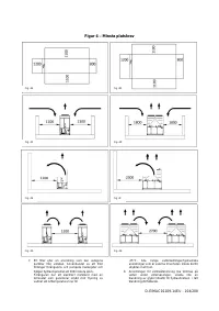
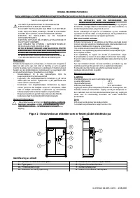
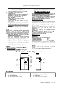
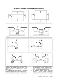
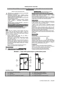
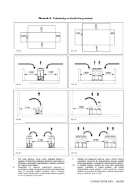
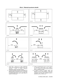
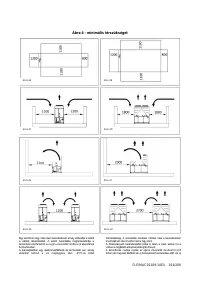
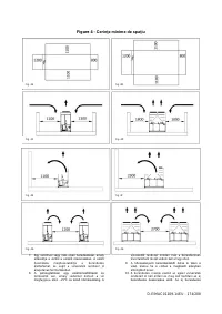
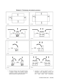
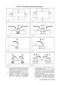
Minimum space requirements
It is fundamental to respect minimum distances on all units in
order to ensure optimum ventilation to the condenser coils.
When deciding where to position the unit and to ensure a
proper air flow, the following factors must be taken into
consideration:
avoid any warm air recirculation
avoid insufficient air supply to the air-cooled condenser.
Both these conditions can cause an increase of condensing
pressure, which leads to a reduction in energy efficiency and
refrigerating capacity.
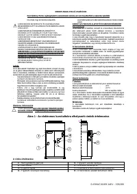
Any side of the unit must be accessible for post-installation
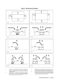
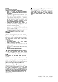
maintenance operations. Figure 4 shows the minimum space
required.
Vertical air discharge must not be obstructed.
If the unit is surrounded by walls or obstacles of the same
height as the unit, this must be installed at a distance no lower
than (see Figure 4C or 4D). If these obstacles are higher, the
unit must be installed at a distance no lower (see Figure 4E or
4F).
Should the unit be installed without observing the
recommended minimum distances from walls and/or vertical
obstacles, there could be a combination of warm air
recirculation and/or insufficient supply to the air-cooled
condenser which could cause a reduction of capacity and
efficiency.
In any case, the microprocessor will allow the unit to adapt
itself to new operating conditions and deliver the maximum
available capacity under any given circumstances, even if the
lateral distance is lower than recommended, unless the
operating conditions should affect personel safety or unit
reliability.
When two or more units are positioned side by side, a distance
of at least (see Figure 4G or 4H) between condenser
banks is recommended.
For further solutions, please consult manufacturer
representative.
Sound protection
When sound levels require special control, great care must be
exercised to isolate the unit from its base by appropriately
applying anti-vibration elements (supplied as an option).
Flexible joints must be installed on the water connections, as
well.
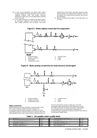
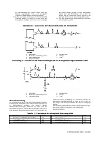
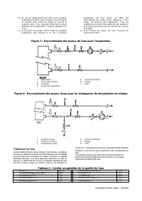
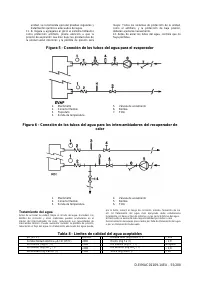
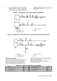
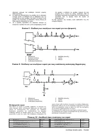
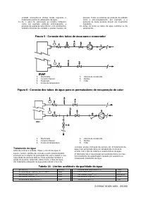
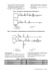
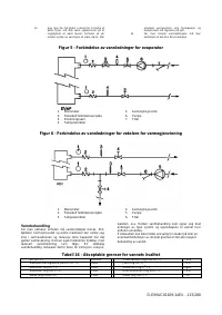
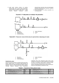
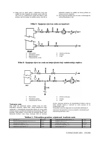
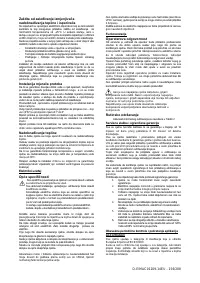
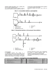
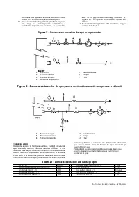
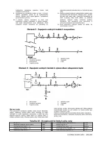
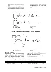
Water piping
Piping must be designed with the lowest number of elbows
and the lowest number of vertical changes of direction. In this
way, installation costs are reduced considerably and system
performance is improved.
The water system must have:
1 Anti-vibrationmountingsinordertoreduce
transmission of vibrations to the structures.
2. Isolating valves to isolate the unit from the water
system during service.
3. Manual or automatic air venting device at the
system’s highest point.; drain device at the system’s
lowest point.
4. Neither the evaporator nor the heat recovery device
must be positioned at the system’s highest point.
5. A suitable device that can maintain the water
system under pressure (expansion tank, etc.).
6. Water temperature and pressure indicators to assist
the operator during service and maintenance.
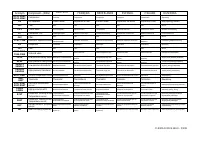
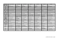
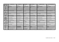
Содержание
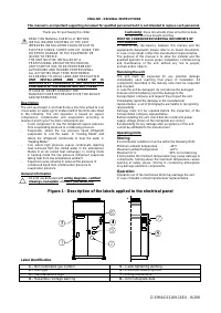
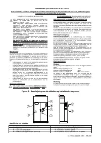
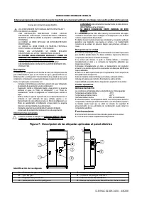
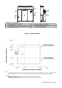
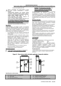
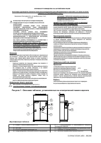
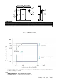
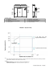
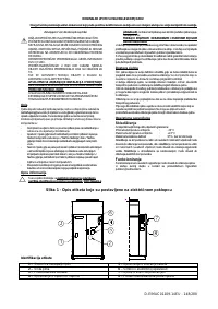
- 88 Описание; электрическими схемами, сертифицированными; При получении агрегата; Хранение; Идентификация табличек
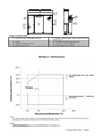
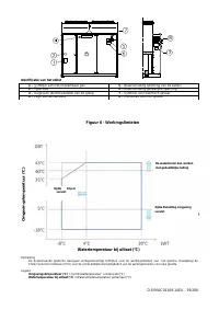
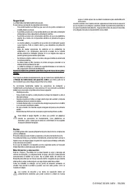
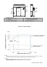
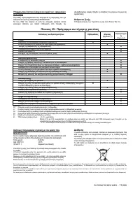
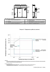
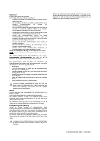
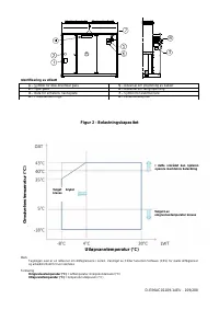
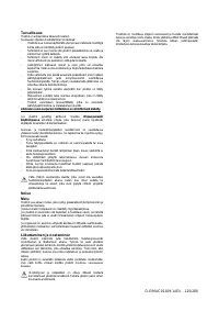
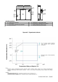
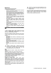
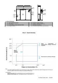
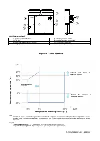
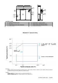
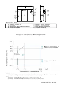
- 89 Рисунок 2 - Предельные рабочие значения; частичной
- 90 Техника безопасности; Руководства по; Шум
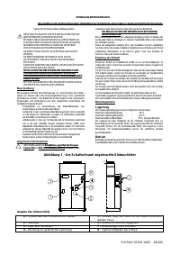
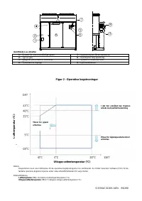
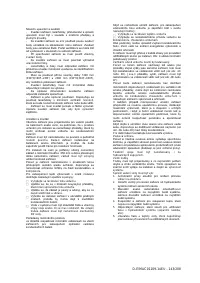
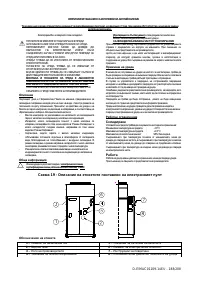
- 91 Рисунок 3 - Подъем агрегата
- 92 : Указания по подъему агрегата
- 93 Монтажная позиция; Требования к месту установки
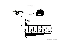
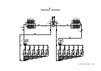
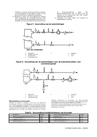
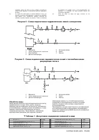
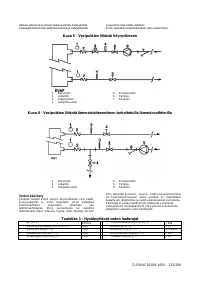
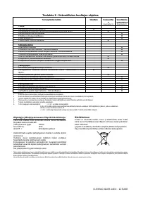
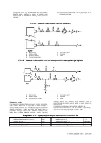
- 95 Рисунок 5 - Схема подключения гидравлических линий к испарителю; рекуперации тепла s; Обработка воды; Таблица 1 - Допустимое содержание примесей в воде
- 96 Электрическая система; Указания общего характера; Эксплуатация агрегата; Обязанности оператора; Сервисное и гарантийное обслуживание
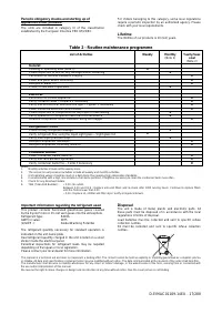
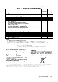
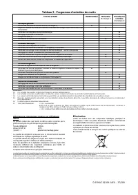
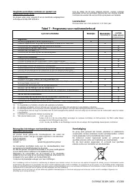
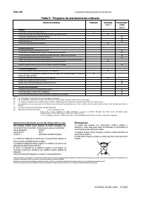
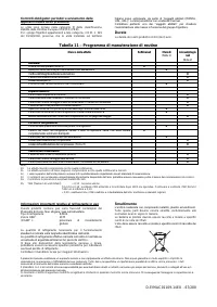
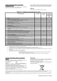
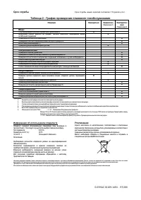
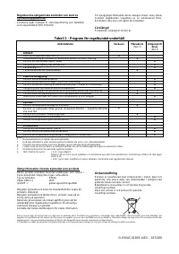
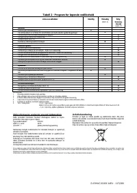
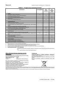
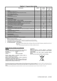
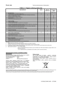
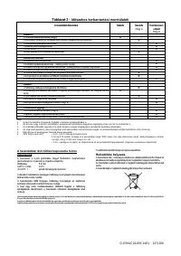
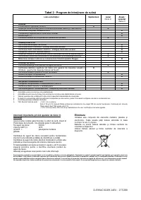
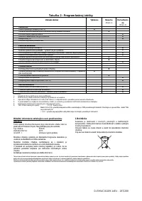
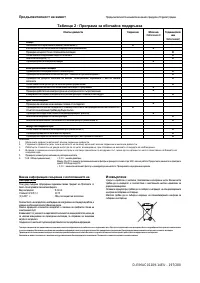
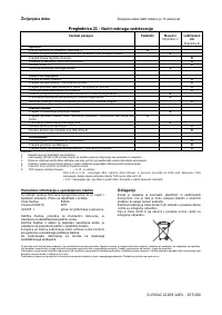
- 97 Срок службы; Таблица 2 - График проведения планового техобслуживания; Операции; Информация об используемом хладагенте; Утилизация


