
Генераторы Telwin MOTOINVERTER 254 CE HONDA 815975 - инструкция пользователя по применению, эксплуатации и установке на русском языке. Мы надеемся, она поможет вам решить возникшие у вас вопросы при эксплуатации техники.
Если остались вопросы, задайте их в комментариях после инструкции.
"Загружаем инструкцию", означает, что нужно подождать пока файл загрузится и можно будет его читать онлайн. Некоторые инструкции очень большие и время их появления зависит от вашей скорости интернета.
safeguards:
Almost all coated electrodes should be connected to the positive
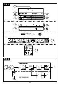
- Thermal relay:
the temperature inside the engine-driven welder
terminal (+) of the engine-driven welder; exceptionally, connection is
is too high. The machine stays on but does not supply any
to the negative terminal (-) for acid coated electrodes.
current until a normal temperature is reached. Reset is
automatic.
Connecting the electrode-holder-clamp welding cable
- ANTI STICK safeguard:
automatically shuts down the welding
On the terminal attach a special clamp to close the exposed part of the
current if the electrode sticks to the material being welded, so
electrode.
that it can be removed manually without ruining the electrode-
This cable should be connected to the terminal with the symbol (
+
)
holder clamp.
Connecting the welding current return cable
- Engine overspeed safeguard:
shuts down the welding current
On the terminal attach a clamp that should be connected to the piece
supply until the engine speed returns to the rated values.
being welded or to the metal bench on which it is placed, as close as
10- Function selector potentiometer and arc-force adjustment:
possible to the join being made.
This cable should be connected to the terminal with the symbol (
-
)
(
TIG welding). In this position the potentiometer enables TIG
welding with scratch strike. HOT START and ARC-FORCE are
Advice:
disabled.
- Screw the welding cable connectors right into the quick connections,
to ensure a perfect electrical contact; otherwise an imperfect contact
(
MMA welding). Positioning the potentiometer between 0
will cause overheating in the connectors and they will quickly
and 100% gives an easy start (HOT START) and it is possibile to
become damaged and inefficient.
adjust the ARC-FORCE for all types of electrodes. At very low
- The welding cables used should be as short as possible.
values an optimal welding dynamic is obtained for “soft”
- Do not use metal structures that are not part of the piece being
electrodes (e.g. rutile, stainless steel), at high values an optimal
welded, to replace the welding current return cable; this could be a
welding dynamic is obtained for “hard” electrodes (e.g. acid, basic,
safety hazard and give an unsatisfactory result for the weld.
cellulose).
11-
Positive quick connection (+) for connecting the welding cable.
12-
Negative quick connection (-) for connecting the welding cable.
6. WELDING: DESCRIPTION OF THE PROCEDURE
- It is essential to follow the electrode manufacturer's instructions as
13-
Terminal for earth connection.
regards the correct polarity and optimal welding current (these
instructions are usually printed on the package containing the
5. INSTALLATION
________________________________________________________________________________
electrodes).
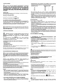
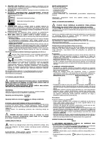
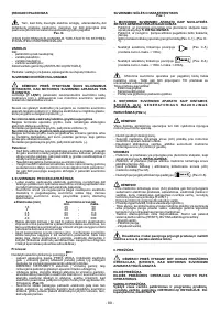
- The welding current should be adjusted according to the diameter of
the electrode being used and the type of join to be made; indicatively,
WARNING! ALL INSTALLATION OPERATIONS AND
the currents used for the different electrode diameters are:
ELECTRICAL CONNECTIONS MUST BE MADE WITH THE
ø Electrode (mm)
Welding current (A)
ENGINE-DRIVEN WELDER SWITCHED OFF COMPLETELY THE
min.
max.
ELECTRICAL CONNECTIONS MUST BE MADE ONLY AND
1,6
25
-
50
EXCLUSIVELY BY EXPERT OR SKILLED PERSONNEL.
2
40
-
80
________________________________________________________________________________
2,5
60
-
110
3,2
80
-
160
SETTING UP THE ENGINE-DRIVEN WELDER
4,0
120
-
200
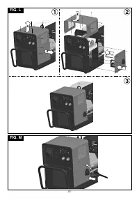
Unpack the engine-driven welder and assemble the separate parts
- Bear in mind that for the same electrode diameter high current
contained in the package.
values will be used for horizontal welding, while lower values should
be used for vertical or overhead welding.
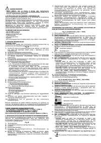
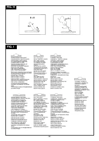
Assembling the clamp-return cable
- As well as being determined by the chosen current intensity, the
Fig. E
mechanical properties of the welded join are also determined by
other welding parameters such as arc length, working speed and
Assembling the electrode-holder clamp-welding cable
position, electrode diameter and quality (to store the electrodes
Fig. F
correctly keep them in a dry place in their original package or in
suitable containers).
POSITIONING THE ENGINE-DRIVEN WELDER
Choose a position to install the engine-driven welder so that there are
Procedure:
no obstructions to the cooling air inlets and outlets; at the same time
make sure there is no intake of conductive powders, corrosive
Position the selector to the correct position
vapours, humidity etc.
Keep at least 1m free space all around the engine-driven welder.
- Keeping the mask IN FRONT OF THE FACE, scratch the tip of the
electrode along the piece to be welded as though you were striking a
______________________________________________
match; this is the most correct way to strike the arc.
WARNING: DO NOT TAP the electrode on the piece; this could
damage the coating, making it difficult to strike the arc.
WARNING! Position the engine-driven welder on a flat
- As soon as the arc has struck, try to keep at a distance from the
surface that will support its weight so that it cannot tipp or shift
piece equivalent to the diameter of the electrode in use and keep this
dangerously.
distance as constant as possible while carrying out the weld;
______________________________________________
remember that the electrode should be inclined at about 20-30
degrees in the direction of progress
(Fig.H)
.
EARTHING THE MACHINE
- At the end of the weld seam take the electrode slightly backwards
________________________________________________________________________________
with respect to the direction of progress, above the crater so that it is
filled, then lift the electrode quickly from the weld pool so that the arc
To prevent electric shock from faulty user apparatus the
is extinguished.
machine must be connected to a fixed earth installation using the
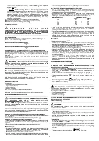
APPEARANCE OF THE WELD SEAM
terminal supplied for this purpose.
Fig. I
Fig. G
7. USING THE ENGINE-DRIVEN WELDER AS A DIRECT
ELECTRICAL CONNECTIONS MUST BE CARRIED OUT ONLY
CURRENT GENERATOR
AND EXCLUSIVELY BY EXPERT OR SKILLED PERSONNEL.
________________________________________________________________________________
- Make sure the machine is connected to an earth stake as described
in section
5. INSTALLATION.
ENGINE
- Make sure that the voltage of the apparatus corresponds with the
As regards:
voltage supplied by the auxiliary outlet.
- checks before use;
- Connect the plug of the tool to the corresponding outlet on the
- starting the engine;
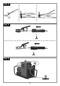
machine (Fig. C-1) - (Fig. D-1).
- using the engine;
- stopping the engine;
- Position the selector to the correct position
(Fig. C-5)
refer to the USER'S HANDBOOK supplied by the engine
(model with I max = 130A).
2
manufacturer.
- Position the selector to the correct position
(Fig. D-6)
Note: the engine is protected against failure due to lack of oil.
(model with I max = 160A, I max = 200A).
2
2
________________________________________________________________________________
CONNECTIONS FOR THE WELDING CIRCUIT
________________________________________________________________________________
The engine-driven welder supplies direct current via the
auxiliary outlet. It is therefore ONLY possible to connect tools with a
WARNING!
BEFORE
MAKING
THE
FOLLOWING
universal motor (brushes).
CONNECTIONS MAKE SURE THE ENGINE-DRIVEN WELDER IS
Examples of such electric tools are:
SWITCHED OFF.
- Electric drills;
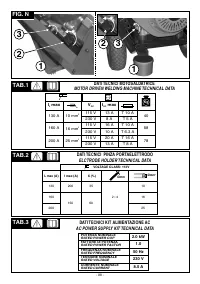
The table
(TAB. 1)
shows the recommended values for the welding
- Angle grinders;
2
cables (in mm ) based on the maximum current supplied by the
- Portable jigsaws.
engine-driven welder.
- Filament lamps.
________________________________________________________________________________
________________________________________________________________________________
- 5 -


