
Триммеры Hitachi CG18DSDL-R4 - инструкция пользователя по применению, эксплуатации и установке на русском языке. Мы надеемся, она поможет вам решить возникшие у вас вопросы при эксплуатации техники.
Если остались вопросы, задайте их в комментариях после инструкции.
"Загружаем инструкцию", означает, что нужно подождать пока файл загрузится и можно будет его читать онлайн. Некоторые инструкции очень большие и время их появления зависит от вашей скорости интернета.


19
English
CAUTION
○
If the batter y is charged while it is heated because it has
been left for a long time in a location subject to direct
sunlight or because the batter y has just been used,
the pilot lamp of the charger lights for 1 second, does
not light for 0.5 seconds (o
ff
for 0.5 seconds). In such a
case,
fi
rst let the batter y cool, then start charging.
○
When the pilot lamp
fl
ickers (at 0.2-second inter vals),
check for and take out any foreign objects in the
charger’s batter y connector. If there are no foreign
objects, it is probable that the batter y or charger is
malfunctioning. Take it to your authorized Ser vice
Center.
○
Since the built-in micro computer takes about 3
seconds to con
fi
rm that the batter y being charged
with UC18YGSL is taken out, wait for a minimum of 3
seconds before reinserting it to continue charging. If
the batter y is reinserted within 3 seconds, the batter y
may not be properly charged.
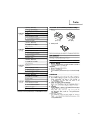
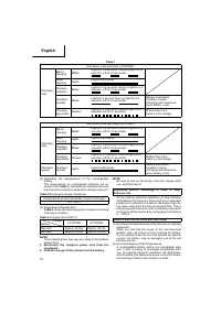
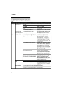
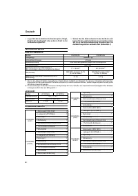
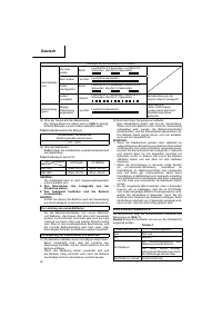
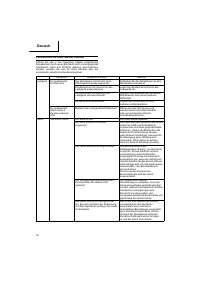
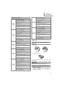
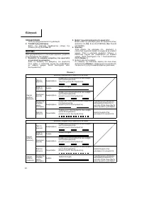
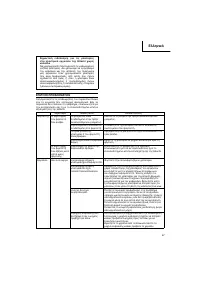
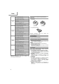
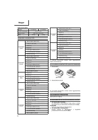
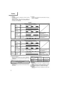
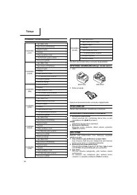
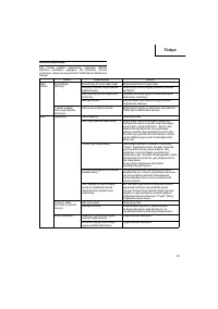
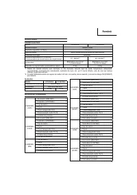
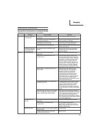
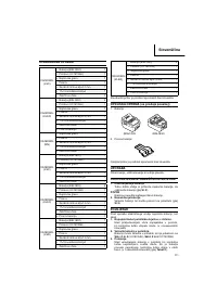
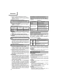
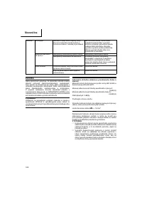
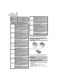
ABOUT
POWER
LAMP
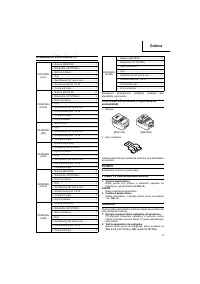
The power lamp indicates various statuses for the tool.
(
Fig.
7
)
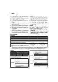
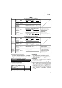
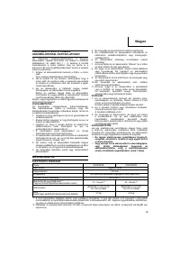
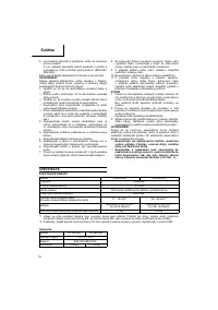
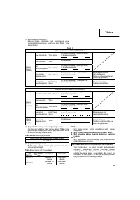
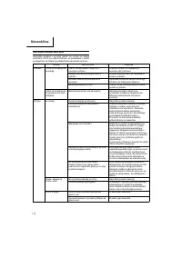
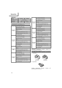
Table
4
shows the various statuses indicated by the power
lamp.
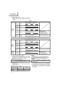
Table
4
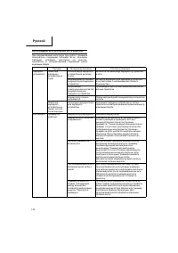
State of lamp
Status of Tool
O
ff
Power
OFF
Red
Power ON
Blinking red
The over-heat protection circuit
of the tool is operating.
The lever is being pressed while
the overload protection circuit of
the tool is operating.
Quickly blinking red
The tool is operating abnormally.
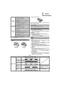
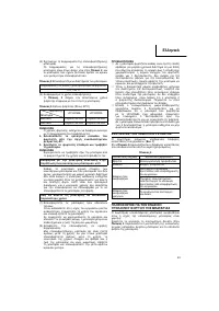
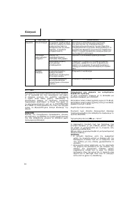
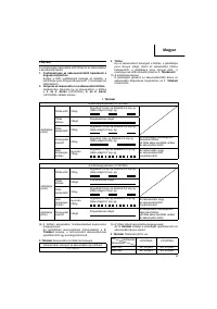
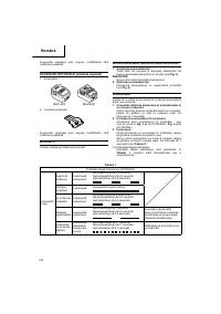
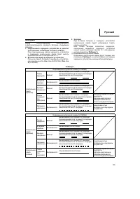
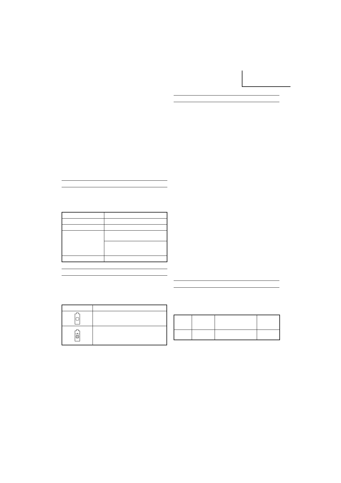
ABOUT
REMAINING
BATTERY
INDICATOR
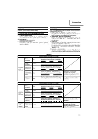
The remaining batter y lamp blinks when the remaining
batter y power is low.
Please charge the tool as soon as possible. The
Table
5
shows the state of remaining batter y indicator lamp and the
batter y remaining power.
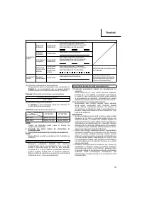
Table
5
State of lamp
Batter y Remaining Power
The batter y remaining power is
enough.
The batter y remaining power is nearly
empty.
Re-charge the batter y soonest
possible.
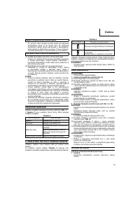
As the remaining batter y indicator shows somewhat
di
ff
erently depending on ambient temperature and batter y
characteristics, read it as a reference.
NOTE
Do not give a strong shock to the switch panel or break
it. It may lead to a trouble.
PRIOR
TO
OPERATION
CAUTION
Pull out batter y before doing any assembly.
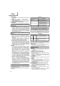
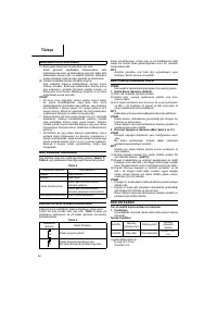
1.
Installing
the
loop
handle
(Fig.
8)
(1) Remove the M6 × 43 bolts (2 pcs.).
(2) Install the loop handle on the main pipe so that it leans
against the housing.
(3) Place the handle
fi
xture at the lower end of the main
pipe and secure it
fi
rmly using M6 × 43 bolts (2 pcs.)
and M6 nuts (2 pcs.).
NOTE
Secure the loop handle in a location that provides a
good grip.
CAUTION
Install the loop handle properly and securely as
instructed in the handling instructions.
If not attached properly or securely, it may come o
ff
and
cause injur y.
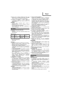
2.
Installing
cover
(See
Fig.
9
and
10)
WARNING
Be sure to install the cover in its designated location.
Failure to heed this warning may result in injur y from
fl
ying stones.
NOTE
Use the supplied hex. bar wrench 4 mm for installation.
(1) Use the supplied D5 tapping screw to install the knife in
the cover. (
Fig.
9
)
(2) Align the two holes in the cover bracket and the cover
and insert two M6 × 25 hex. socket button bolts. (The
cover bracket is installed in the motor case.)
(3) Place the cover holder on the underside of the cover and
use the supplied hex. bar wrench 4 mm to alternately
tighten the two M6 × 25 hex. socket button bolts until
they are properly tightened.
CAUTION
○
Take care to avoid cutting yourself on the knife inside
the cover.
○
Install the cover and knife properly and securely as
instructed in the handling instructions.
If not attached properly or securely, they may come o
ff
and cause injur y.
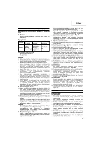
NYLON
HEAD
Installation
of
semi
-
auto
nylon
head
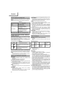
1.
Function
Automatically feeds more nylon cutting line when it is
tapped.
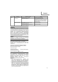
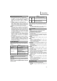
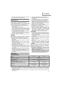
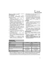
Speci
fi
cations
Code
No.
Type of
attaching
screw
Direction of rotation
Size of
attaching
screw
333903
Female
screw
Counterclockwise
M10×
P1.25-LH
Applicable nylon cord
Cord
diameter:
1.4 mm
Length: 6 m
CAUTION
○
The case must be securely attached to the cover.
○
Check the cover, case and other components for cracks
or other damage.
○
Check the case and button for wear.
If the wear limit mark on the case is no longer visible or
there is a hole in the bottom of the button, change the
new parts immediately. (
Fig.
14
)
000Book̲CG14DSDL̲EE.indb 19
000Book̲CG14DSDL̲EE.indb 19
2011/06/17 14:23:03
2011/06/17 14:23:03


