
Сверлильные станки Bosch PBD 40 - инструкция пользователя по применению, эксплуатации и установке на русском языке. Мы надеемся, она поможет вам решить возникшие у вас вопросы при эксплуатации техники.
Если остались вопросы, задайте их в комментариях после инструкции.
"Загружаем инструкцию", означает, что нужно подождать пока файл загрузится и можно будет его читать онлайн. Некоторые инструкции очень большие и время их появления зависит от вашей скорости интернета.


English |
21
Bosch Power Tools
1 619 929 L21 | (12.9.13)
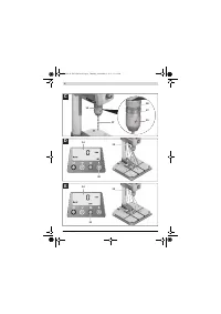
Note:
When inserting drill bits with small diameters, set the
tool holder beforehand approximately to the drill bit diame-
ter. Otherwise, it is possible that the drill bit is not inserted
centred.
Removing
– Turn the securing ring
27
toward “UNLOCK”.
– Turn the clamping sleeve
29
clockwise until the tool bit
17
can be removed.
Operation
Before any work on the machine itself, pull the mains
plug.
After each adjustment on the machine, retighten the
screws and clamping levers.
Preparing for Operation
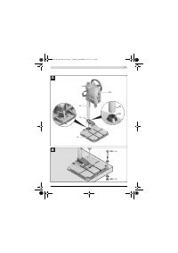
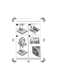
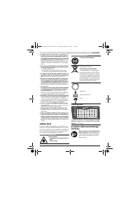
Illuminating the Work Area (see figure D)
Provide for sufficient lighting of the direct working area.
– To
activate the display 14
, turn the On/Off switch
13
to
position
.
– Switch on the illumination unit
22
with button
30
.
The indication “
Light
” is shown on display
14
.
Correctly positioning the workpiece (see figure E)
A laser cross indicates the exact drilling location.
– To
activate the display 14
, turn the On/Off switch
13
to
position
.
– Switch on the laser unit
22
with button
31
.
The indication “
Laser
” is shown on display
14
.
– Align your mark on the workpiece with the laser cross.
Clamping the Workpiece (see figures F1
–
F2)
To ensure optimum working safety, the workpiece must al-
ways be firmly clamped.
Do not saw workpieces that are too small to clamp.
– Position the workpiece with help of the laser cross (see
“Correctly positioning the workpiece”, page 21).
– Loosen the quick-clamping lever
2
on the quick-clamping
device
3
.
– Allow the quick-clamping device to face against the work-
piece. Turn the quick-clamping lever
2
in clockwise direc-
tion until the workpiece is firmly clamped.
– After drilling, loosen quick-clamping lever
2
in anticlock-
wise direction.
– Turn the quick-clamping device
3
aside and remove the
workpiece.
The parallel guide
19
is used for securing larger workpieces
against turning.
– Loosen the wing bolts
20
of parallel guide
19
and insert the
parallel guide into the grooves of base plate
1
.
– Retighten the wing bolts again.
– Clamp the workpiece with the quick-clamping device
3
.
Note:
Use a machine vice (e.g. Bosch MS 80) to clamp small-
er workpieces.
Adjusting the Height of the Motor Unit (see figure G)
Do not adjust the height of the motor unit during oper-
ation. Actuate clamping lever 7 only when the hand-
wheel is in the starting position.
This safety measure
prevents possible injury.
The height of the motor unit
12
can be adjusted dependent on
the length of the application tool and the size of the work-
piece.
Note:
After adjusting the height of the motor unit, the posi-
tioning of the workpiece must be checked again with the laser
cross. Realign the workpiece, if required.
When clamping lever
7
is open, a brake prevents the motor
unit
12
from accidental lowering. Occasionally check the
clamping force of the brake and readjust it as required (see
“Adjusting the Brake of the Motor Unit”, page 23).
– Make sure that the handwheel
11
is in the starting posi-
tion.
– Grasp the handwheel
11
with one hand and with the other
hand, loosen clamping lever
7
in anticlockwise direction.
– Adjust the height of motor unit
12
with the handwheel ac-
cording to the inserted application tool and height of the
workpiece.
– Tighten clamping lever
7
again in clockwise direction.
Note:
Clamping lever
7
is indexed (adjustable), allowing it to
be set to an ergonomically favourable and space-saving posi-
tion.
With the clamping lever tightened, pull its lever away from the
motor unit, turn it to the desired position and allow it to en-
gage again.
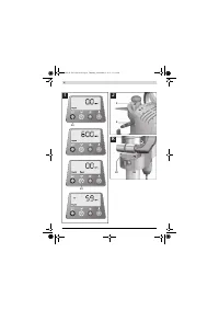
Starting Operation
Observe correct mains voltage! The voltage of the pow-
er source must agree with the voltage specified on the
nameplate of the machine. Power tools marked with
230 V can also be operated with 220 V.
Switching On
To save energy, only switch the power tool on when using it.
– To
activate the display 14
, turn the On/Off switch
13
to
position
.
– To
start the machine
, turn the On/Off switch
13
to
position
.
The speed can now be set (see “Adjusting the Speed”,
page 22).
Switching Off
– To
end the drilling
, turn the On/Off switch
13
to
position
.
or
– To
completely shut-off
the machine, turn the On/Off
switch
13
to position “
0
”.
Note:
The power tool is now currentless. All current set-
tings are deleted.
Quick-Stop Function
The Quick-Stop function enables swift switching off, e.g.,
when the application tool is jammed or locked-up in the work-
piece.
OBJ_BUCH-1183-006.book Page 21 Thursday, September 12, 2013 11:11 AM
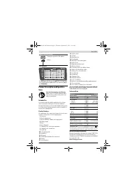
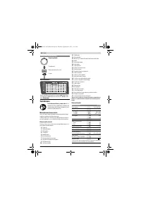
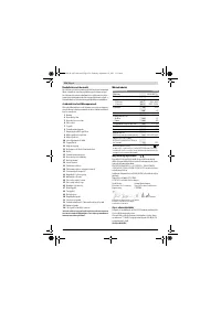
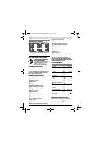
Содержание
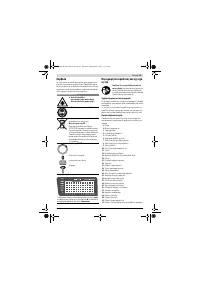
- 139 Символы
- 140 Применение по назначению
- 141 Заявление о соответствии; Сборка; Комплект поставки
- 142 Работа с инструментом; Подготовка к эксплуатации; Включение электроинструмента
- 143 Установка числа оборотов
- 144 Транспортировка; Техобслуживание и сервис; Техобслуживание и очистка
- 145 Утилизация; Українська; Вказівки з техніки безпеки; Загальні застереження для електроприладів
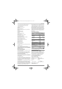
Характеристики

Остались вопросы?Не нашли свой ответ в руководстве или возникли другие проблемы? Задайте свой вопрос в форме ниже с подробным описанием вашей ситуации, чтобы другие люди и специалисты смогли дать на него ответ. Если вы знаете как решить проблему другого человека, пожалуйста, подскажите ему :)


