Сварочное оборудование Telwin TELMIG 161 1 TURBO - инструкция пользователя по применению, эксплуатации и установке на русском языке. Мы надеемся, она поможет вам решить возникшие у вас вопросы при эксплуатации техники.
Если остались вопросы, задайте их в комментариях после инструкции.
"Загружаем инструкцию", означает, что нужно подождать пока файл загрузится и можно будет его читать онлайн. Некоторые инструкции очень большие и время их появления зависит от вашей скорости интернета.


- 8 -
spool gun button and wait for the end of the wire to pass completely
-
welding voltage range :
24-30V
through the wire guide hose and for 10-15 cm to come out of the
-
suitable gases :
Ar 99.9%
front of the torch, release the torch button.
The contact tip should generally be 5-10mm inside the nozzle, the
higher the arc voltage the further inside; the length of free wire (stick-
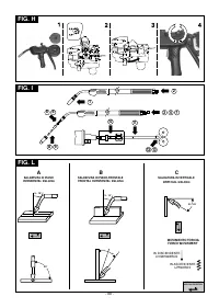
REPLACING THE LINER IN THE TORCH (FIG. I)
out) should normally be between 10 and 12mm.
Before proceeding to replace the hose, lay out the torch cable straight
In MANUAL MODE (“PRG 0”), once the wire feed rate and arc voltage
without any bends.
parameters have been selected correctly (i.e. with compatible values),
the selected value of the reactance is immaterial.
Coiled hose for steel wires
1-
Unscrew the nozzle and contact tip on the torch head.
Application:
Horizontal welding with thicknesses of at least 3-4mm
(very fluid pool); execution rate and deposit rate are very high (high
2-
Unscrew the hose locking nut on the central connector and remove
heat transfer).
the old hose.
3-
Insert the new hose into the cable-torch duct and push it gently
WIRE WELDING
until it comes out of the torch head.
PULSE ARC TRANSFER MODE (WHERE PROVIDED)
4-
Tighten up the hose locking nut by hand.
This is a “controlled” transfer situated in the “spray arc” transfer area
5-
Trim off all the excess protruding hose pressing it slightly; remove it
(modified spray arc) and therefore has the advantages of speedy
from the torch cable again.
melting and lack of projections, extending to significantly low current
6-
Smooth the part where the hose was cut and reinsert it into the
values so as to satisfy many typical “short arc” applications as well.
cable-torch duct.
Every current impulse corresponds to the separation of a single drop
7-
Tighten up the nut again using a spanner.
from the wire electrode; the phenomenon occurs with a frequency that
8-
Reassemble the contact tip and nozzle.
is proportional to the wire feed rate with the variation rule related to the
type and diameter of the wire itself (typical frequency values: 30-
Synthetic hose for aluminium wires
300Hz).
Carry out operations
1, 2, 3
as given for the steel hose (ignore
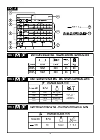
Carbon and mild steels
operations
4, 5, 6, 7, 8
).
- Suitable wire diameter:
0.8-1.6mm
9-
Re-tighten the contact tip for aluminium, making sure it comes into
-
Welding current range:
60-360A
contact with the hose.
-
Arc voltage range :
18-32V
10-
At the other end of the hose (torch connector end) insert the brass
-
Suitable gases :
mix Ar/CO , Ar/CO /O (Co max 20%)
2
2
2
2
nipple and the OR ring and, keeping slight pressure on the hose,
Stainless steels
tighten the hose locking nut.
- Suitable wire diameter:
0.8-1.2mm
The excess part of the hose will be removed to size later on (see
-
Welding current range:
50-230A
(13)
).
-
Welding voltage range :
17-26V
Extract the capillary pipe for steel hoses from the wire feeder torch
-
Suitable gases :
mix Ar/O , Ar/CO (1-2%)
connector.
2
2
Aluminium and alloys
11-
THE CAPILLARY PIPE IS NOT REQUIRED for aluminium hoses of
- Suitable wire diameter:
0.8-1.6mm
diameter 1.6-2.4mm (coloured yellow); the hose is therefore
-
Welding current range:
40-320A
inserted into the torch connector without it.
-
welding voltage range :
17-28V
Cut the capillary pipe for aluminium hoses of diameter 1-1.2mm
-
suitable gases :
Ar 99.9%
(coloured red) to approx. 2mm shorter than the steel pipe, and
Normally the contact pipe should be 5-10mm inside the nozzle, the
insert it into the free end of the hose.
higher the arc voltage, the further inside; the length of free wire (stick-
12-
Insert and lock the torch into the wire feeder connector, mark the
out) will normally be between 10 and 12mm.
hose at 1-2mm from the rollers, take the torch out again.
13-
Cut the hose to the required size, without distorting the inlet hole.
Application
: “horizontal” welding on medium-low thicknesses and on
Reassemble the torch in the wire feeder connector and assemble
heat-sensitive materials,
particularly suitable for welding light
the gas nozzle
alloys (aluminium and its alloys) also on thicknesses below 3mm
.
6. WIRE WELDING
Short arc
ADJUSTING THE WELDING PARAMETERS
The melting of the electrode wire and the detachment of the drop is
Shielding gas
produced by repeated short circuits (up to 200 times per second) from
shielding gas flow rate should be:
the tip of the wire to the molten pool.
short arc:
8-14 l/min
depending on welding current intensity and nozzle diameter.
Carbon and mild steels
- Suitable wire diameter:
0.6-1.2mm
Welding current
- Welding current range:
40-210A
Is determined for a given wire diameter by its own advancement speed.
-
Arc voltage range:
13-23V
Remember that for a given current the wire advancement speed is
- Suitable gases:
CO , mix Ar/CO , Ar/CO /O
2
2
2
2
inversely proportional to the diameter used.
Stainless steels
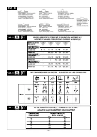
Approximate values for the current in manual welding mode for the
- Suitable wire diameter:
0.8-1mm
most commonly used wires are given in the table (
TAB. 5
).
- Welding current range:
40-160A
-
Arc voltage range:
14-20V
Arc voltage
- Suitable gases:
mix Ar/O , Ar/CO (1-2%)
Arc voltage can be adjusted by the operator by turning the encoder
2
2
Aluminium and alloys
knob (FIG.C (5)); it adjusts itself to the chosen wire feed rate (current)
- Suitable wire diameter:
0.8-1.6mm
according to the diameter of the wire being used and the type of
- Welding current range:
75-160A
protective gas, progressively according to the following relationship,
-
Arc voltage range:
16-22V
which gives an average value:
- Suitable gases:
Ar 99.9%
U = (14 + 0,05 x l )
2
2
- Wire stick out: 5-12mm
where :U = arc voltage in volts;
2
Generally, the
contact tip
should be flush with the nozzle or protrude
l = welding current in amperes.
2
slightly when using the thinnest wires and lowest arc voltages; the
length of free wire (stick-out) will normally be between 5 and 12mm.
Weld quality
The quality of the weld seam is higher when less spatter is produced.
Application:
Welding in all positions, on thin material or for the first
this is determined principally by a correct balance of the welding
passage in bevelled edges, with the advantage of limited heat transfer
parameters: current (wire speed), wire diameter, arc voltage etc., as
and highly controllable pool.
well as a correct choice of choke intakes.
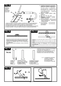
In the same way the torch position must comply with the data in figure
Note:
SHORT ARC transfer for welding aluminium and alloys should
(FIG. L)
in order to avoid excessive spatter and faults on the weld
be used with great care (especially with wires of diameter >1mm)
seam. The weld speed (i.e. the advancement speed along the joint) is
because the risk of melting defects may arise.
also a determining factor for the correct execution of the seam. This is
particularly important for good penetration and correct shape of the
WIRE WELDING
seam.
SPRAY ARC TRANSFER MODE
The most common welding flaws are summarized in
TAB.8.
Higher voltages and currents than for "short arc" are used here to
achieve the melting of the wire. The wire tip does not come into contact
TIG WELDING
with the molten pool; an arc forms from the tip and through it flows a
TIG welding is a welding procedure that exploits the heat produced by
stream of metallic droplets. These are produeced by the continuous
the electric arc that is struck, and maintained, between a non-
melting of the electrode wire without short-circuits involved.
consumable electrode (tungsten) and the piece to be welded. The
Carbon and mild steels
tungsten electrode is supported by a torch suitable for transmitting the
- Suitable wire diameter:
0.8-1.6mm
welding current to it and protecting the electrode itself and the weld
-
Welding current range:
180-450A
pool from atmospheric oxidation, by the flow of an inert gas (usually
-
Arc voltage range :
24-40V
argon: Ar 99.5) which flows out of the ceramic nozzle
(FIG. M)
.
-
Suitable gases :
mix Ar/CO , Ar/CO /O
2
2
2
To achieve a good weld it is absolutely necessary to use the exact
Stainless steels
electrode diameter with the exact current, see the table
(TAB.6).
- Suitable wire diameter:
1-1.6mm
The electrode usually protrudes from the ceramic nozzle by 2-3mm,
-
Welding current range:
140-390A
but this may reach 8mm for corner welding.
-
Welding voltage range :
22-32V
Welding is achieved by fusion of the edges of the joint. For properly
-
Suitable gases :
mix Ar/O , Ar/CO (1-2%)
2
2
prepared thin pieces (up to about 1mm) weld material is not needed
Aluminium and alloys
(FIG. N)
.
- Suitable wire diameter:
0.8-1.6mm
For thicker pieces it is necessary to use filler rods of the same
-
Welding current range:
120-360A
composition as the base material and with an appropriate diameter,


