Сварочное оборудование Telwin TELMIG 161 1 TURBO - инструкция пользователя по применению, эксплуатации и установке на русском языке. Мы надеемся, она поможет вам решить возникшие у вас вопросы при эксплуатации техники.
Если остались вопросы, задайте их в комментариях после инструкции.
"Загружаем инструкцию", означает, что нужно подождать пока файл загрузится и можно будет его читать онлайн. Некоторые инструкции очень большие и время их появления зависит от вашей скорости интернета.


- 6 -
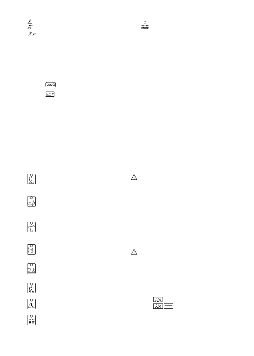
-
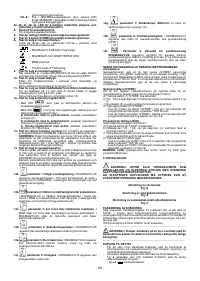
: MIG/MAG/FLUX in SHORT/SPRAY ARC.
-
: MMA electrode.
14i-
parameter 9: Pause time in MIG/MAG/FLUX
spot-
welding regulates the duration of the pause between one spot-
-
: TIG-DC with LIFT strike.
weld and the next. When the setting is 0 sec, in order to carry out
9-
Key for selecting welding process.
the next spot-weld it is necessary to release the torch button and
When the machine is in MIG/MAG/FLUX mode it is possible to
then press it again.
choose between 2-stroke and 4-stroke control or with spot-
welding timer ( SPOT).
S T O R I N G A N D R E C A L L I N G C U S T O M I S E D M I G / M AG
10- Key for selecting type of material.
PROGRAMS
Sets the operating mode according to the material or the
Introduction
procedure.
The welding machine can be used to (STORE) customised work
Only active if in synergy (13).
programs relating to a set of valid parameters for a particular welding
11-
Key for selecting wire diameter is used for setting wire
job. Each stored program can be recalled (LOAD) at any time so that
diameter.
For a diameter of 1.2mm it is necessary to press the
the user finds the welding machine “ready-to-use” for a specific job that
button until both LED's corresponding to diameters of 0.6 and
has been optimised previously. It is possible to store 9 customised
0.8mm light up.
programmes in the welding machine.
Only active if in synergy (13).
12-
Key for selecting remote control.
Storage procedure (STORE)
After adjusting the welding machine for optimal operation with a given
- When LED
is on, the controls on the welding machine
type of weld proceed as follows
(FIG.C)
:
panel are enabled.
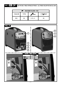
a) Press button
(7)
“STORE” for 3 seconds.
b) “
St_
”will appear on the display
(4)
with a number between 1 and 9.
- When LED
is on, adjustments can only be carried out by
c) Turn the knob
(5)
to choose the desired programme number for
the remote control:
storage.
a) single potentiometer control:
replaces encoder operation
d) Press key
(7)
again “STORE”:
(5).
- if the STORE key is pressed for more than 3 seconds, the
b) control with two potentiometers:
replaces encoder
program has been stored correctly. “
YES
” appears on the display;
operation (5) and the auxiliary parameter function.
- if the STORE key is pressed for less than 3 seconds, the program
c) pedal remote control:
replaces encoder operation (5) in TIG
has not been stored. “
no
” appears on the display.
mode.
13- Key for selecting synergy welding.
To set synergy operation of
Loading procedure (LOAD)
the machine in MIG/MAG welding it is necessary to press the
Proceed as follows
(
see
FIG.C)
:
button.
a) Press button
(6)
“LOAD” for 3 seconds.
WARNING!
Even though the machine allows you to set every
b) “
Ld_
”will appear on the display
(4)
with a number between 1 and 9.
welding parameter freely, there are par ticular parameter
c) Turn the knob
(5)
to choose the number used to store the
combinations that may have no meaning from the electrical or
programme that is now to be
used.
welding point of view. The welding machine will not break down
d) Press key
(6)
“LOAD” again:
however, but it may not operate according to the incorrect setting.
- if the LOAD key is pressed for more than 3 seconds, the program
14- Key for selecting welding parameters.
has been loaded correctly. “
YES
” appears on the display;
Pressing the key repeatedly will light up one of the LED's from
- if the LOAD key is pressed for less than 3 seconds, the program
(14a) to (14i) associated with a specific parameter. The setting for
has not been loaded. “
no
” appears on the display.
the value of each activated parameter is made using the
ENCODER (5) and is shown on the display (4).
NOTE:
during operations with the “store” and “load” keys the prg.
Note: Parameters that cannot be modified by the operator,
depending on whether you are working with a synergy programme
5. INSTALLATION
or in manual mode, are automatically excluded from the selection;
the corresponding LED will not light up.
______________________________________________________
WARNING! CARRY OUT ALL INSTALLATION OPERATIONS
AND ELECTRICAL CONNECTIONS WITH THE WELDING
14a-
parameter 1: Selects the welding voltage.
In
MACHINE COMPLETELY SWITCHED OFF AND DISCONNECTED
MIG/MAG/FLUX it regulates the welding voltage in Volts or the
FROM THE POWER SUPPLY OUTLET.
arc correction in synergy (only for MIG/MAG).
THE ELECTRICAL CONNECTIONS MUST BE MADE ONLY AND
During welding it displays the power source output voltage.
EXCLUSIVELY BY AUTHORISED OR QUALIFIED PERSONNEL.
______________________________________________________
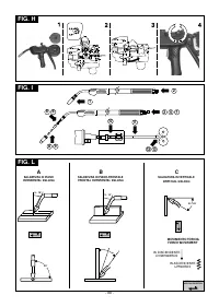
Assembling the protective mask
14b-
parameter 2: Sets the wire feed rate or welding
Fig. D
current. In
MIG/MAG/FLUX it is the wire feed rate in metres per minute. In
Assembling the return cable-clamp
MMA it is the welding current in amps. During welding it displays
Fig. E
the power source output current.
Assembling the welding cable-electrode holder clamp
Fig. F
14c-
parameter 3: Arc force or Electronic reactance.
In
Locate the welding machine in an area where openings for cooling air
MMA it is arc force or arc penetration regulation. In
are not obstructed (forced circulation with fan), leave at least 250mm
MIG/MAG/FLUX it has a similar meaning but is called electronic
free space around the welding machine; check that conductive dusts,
reactance.
corrosive vapours, humidity etc., will not enter welding machine.
______________________________________________________
14d-
parameter
4:
Acceleration
slope-up:
In
WARNING: Position the welding machine on a flat surface
with sufficient carrying capacity for the weight of the welding
MIG/MAG/FLUX it regulates the gradient of the acceleration
machine, to prevent tipping or hazardous movement.
slope-up of the wire feeder moter.
______________________________________________________
CONNECTION TO THE MAIN POWER SUPPLY
14e-
parameter 5: Burn-back time
in MIG/MAG/FLUX it
Warning
- Before making any electrical connection, make sure the rating data
regulates the time interval elapsing between when the wire
of the welding machine correspond to the mains voltage and
stops and the output current falls to zero.
frequency available at the place of installation..
- The welding machine should only be connected to a power supply
system with the neutral conductor connected to earth.
14f-
parameter 6: Postgas.
in MIG/MAG/FLUX it regulates
the postgas time in seconds.
14g-
parameter 7: Slope-down.
In MIG/MAG it is the slope-
- To comply with the requirements of the EN 61000-3-11 (Flicker)
down time (only in synergy (13)).
standard we recommend connecting the welding machine to
interface points of the power supply that have an impedance of less
than Zmax =0.18 ohm.
14h-
parameter 8: Spot time.
In MIG/MAG/FLUX it regulates
PLUG AND OUTLET
the welding current duration in SPOT-welding.
Connect a normalised plug
(2P + T)
having sufficient capacity- to the
power cable and prepare a mains outlet fitted with fuses or an
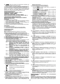
- To ensure protection against indirect contact use residual current
devices of the following types:
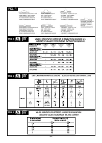
-
Type A (
) for single phase machines;
-
Type B (
) for 3-phase machines.


