Электропилы Bosch GCM 12 SD - инструкция пользователя по применению, эксплуатации и установке на русском языке. Мы надеемся, она поможет вам решить возникшие у вас вопросы при эксплуатации техники.
Если остались вопросы, задайте их в комментариях после инструкции.
"Загружаем инструкцию", означает, что нужно подождать пока файл загрузится и можно будет его читать онлайн. Некоторые инструкции очень большие и время их появления зависит от вашей скорости интернета.


34
| English
1 609 92A 0XM | (5.12.14)
Bosch Power Tools
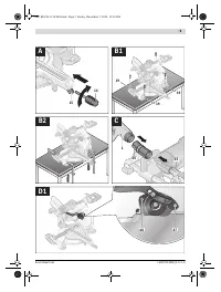
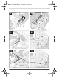
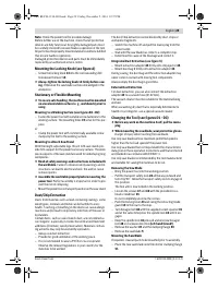
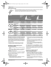
Checking and Adjusting the Basic Adjustment
To ensure precise cuts, the basic adjustment of the machine
must be checked and adjusted as necessary after intensive
use.
A certain level of experience and appropriate specialty tools
are required for this.
A Bosch after-sales service station will handle this mainte-
nance task quickly and reliably.
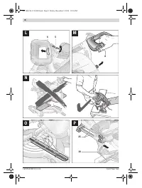
Setting the Standard Bevel Angle 0 ° (Vertical)
– Bring the machine into the transport position.
– Turn the saw table
18
to the 0 ° detent
17
. The lever
15
must be felt to engage in the detent.
Checking:
(see figure S1)
– Set an angle gauge to 90 ° and place it on the saw table
18
.
The leg of the angle gauge must be flush with the saw blade
9
over the complete length.
Adjusting:
(see figure S2)
– Loosen the lock lever
16
.
– Loosen set screws
60
and
61
with the supplied open-end
spanner
3
(10 mm).
– Loosen set screw
62
(approx. 3 turns) with the supplied
hex key
35
(4 mm).
– Screw set screw
59
(10 mm) in or out until the leg of the
angle gauge is flush with the saw blade over the complete
length.
– Retighten the lock lever
16
again.
Afterwards, tighten set screw
62
first, and then set screws
60
and
61
.
When the angle indicators
33
and
24
are not in line with the 0 °
marks of scale
32
after adjusting, loosen the fastening screws
of the angle indicators with the supplied cross-head screwdriv-
er
35
and align the angle indicators alongside the 0 ° marks.
Setting the Standard 45 ° Bevel Angle (Leftward)
– Bring the power tool into the working position.
– Turn the saw table
18
to the 0 ° detent
17
. The lever
15
must be felt to engage in the detent.
– Pull the left fence extension
21
completely outward.
– Loosen the lock lever
16
and tilt the tool arm leftward to
the stop (45 °) by the handle
7
.
Checking:
(see figure T1)
– Set an angle gauge to 45 ° and place it on the saw table
18
.
The leg of the angle gauge must be flush with the saw blade
9
over the complete length.
Adjusting:
(see figure T2)
– Screw set screw
63
(10 mm) in or out until the leg of the
angle gauge is flush with the saw blade over the complete
length.
– Retighten the lock lever
16
again.
When the angle indicators
33
and
24
are not in line with the
45 ° marks of scale
32
after adjusting, firstly once more check
the 0 ° setting for the bevel angle and the angle indicators.
Then repeat the adjustment of the 45 ° bevel angle.
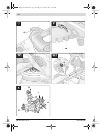
Adjusting the Clamping Force of Lock Lever 16
(see figure T2)
The clamping force of lock lever
16
can be readjusted.
Checking:
– The clamping force of the clamping lever must securely
hold the position of the tool arm at any bevel angle.
Adjusting:
– Loosen the lock lever
16
.
– Turn set screw
64
in anticlockwise direction with the sup-
plied open-end spanner
3
(17 mm) to reduce the clamping
force, or increase the clamping force by turning in clock-
wise direction.
– Adjust a vertical bevel angle, retighten lock lever
16
and
check if the desired clamping force has been reached.
Adjusting the Clamping Force of Clamp 5 (see figure U)
The clamping force of the handle clamp
5
can be readjusted.
Checking:
– The clamping force of the clamp must securely hold the
handle in any of the 4 possible positions.
Adjusting:
– Open clamp
5
.
– Turn both set screws
65
in anticlockwise direction with the
supplied hex key
2
(1.5 mm) to reduce the clamping force,
or increase the clamping force by turning in clockwise di-
rection.
Always adjust both set screws to the same height.
– Shut clamp
5
and check if the desired clamping force has
been reached.
Aligning the Angle Indicator (Horizontally) (see figure V)
– Bring the power tool into the working position.
– Turn the saw table
18
to the 0 ° detent
17
. The lever
15
must be felt to engage in the detent.
Checking:
The angle indicator
66
must be in alignment with the 0 ° mark
of the scale
40
.
Adjusting:
– Loosen the fastening screw of the angle indicator with the
supplied cross-head screwdriver
35
and align the angle in-
dicator alongside the 0 ° mark.
– Retighten the screw again.
Aligning the Fence
– Bring the machine into the transport position.
– Turn the saw table
18
to the 0 ° detent
17
. The lever
15
must be felt to engage in the detent.
Checking:
(see figure W1)
– Adjust an angle gauge to 90 ° and position it flush with the
saw blade
9
between the fence
20
and the saw blade on
the saw table
18
.
The leg of the angle gauge must be flush with the fence over
the complete length.
OBJ_BUCH-1130-003.book Page 34 Friday, December 5, 2014 12:37 PM
Содержание
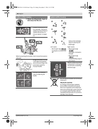
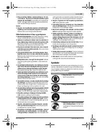
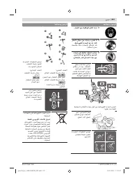
- 231 или подвижных частей электроинструмента.
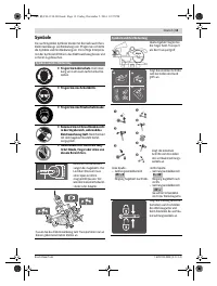
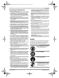
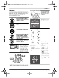
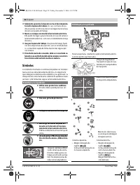
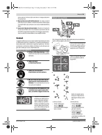
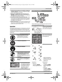
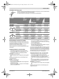
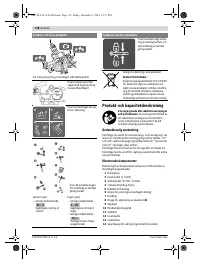
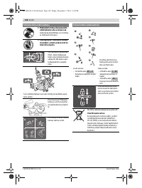
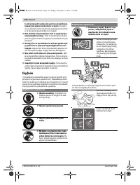
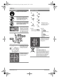
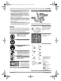
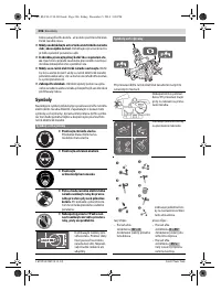
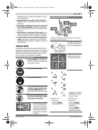
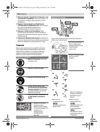
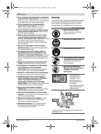
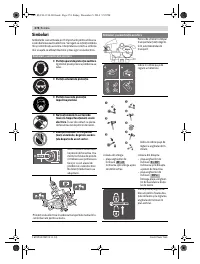
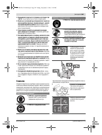
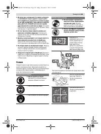
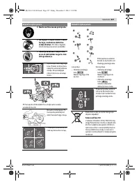
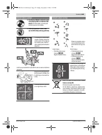
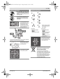
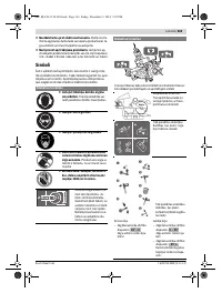
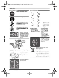
- 232 Не становитесь на электроинструмент.; Символы; Символы и их значение
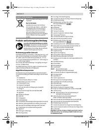
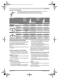
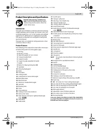
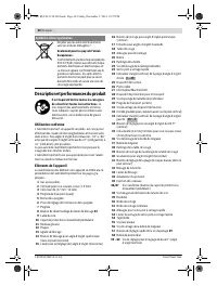
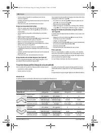
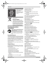
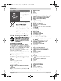
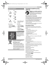
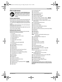
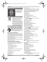
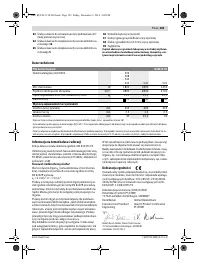
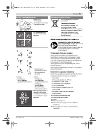
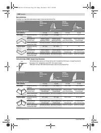
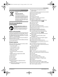
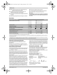
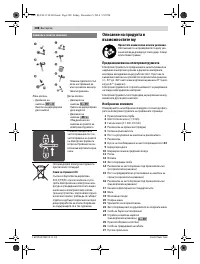
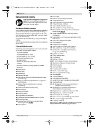
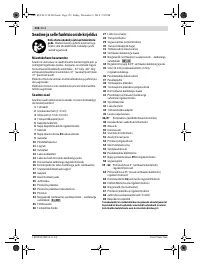
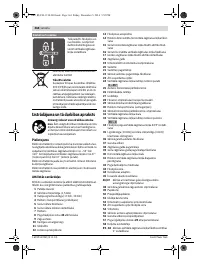
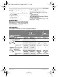
- 234 Описание продукта и услуг; Применение по назначению
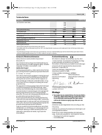
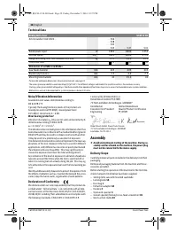
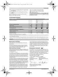
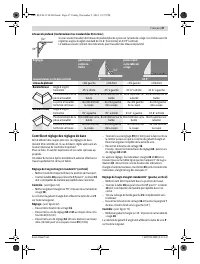
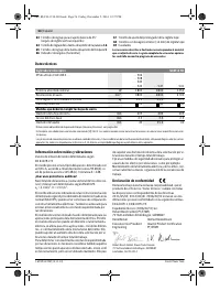
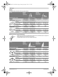
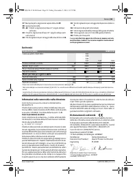
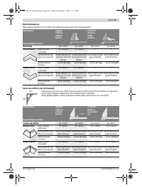
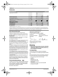
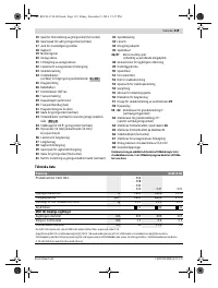
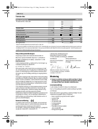
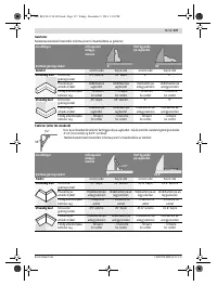
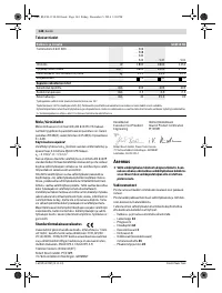
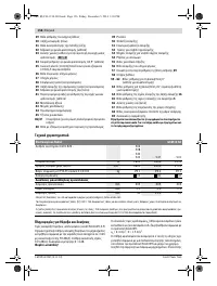
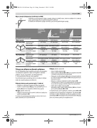
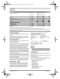
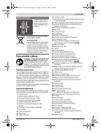
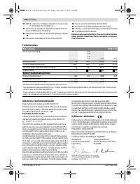
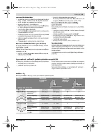
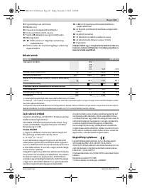
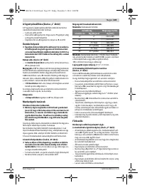
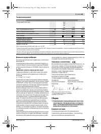
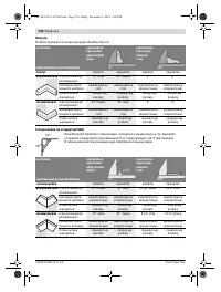
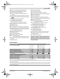
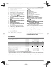
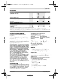
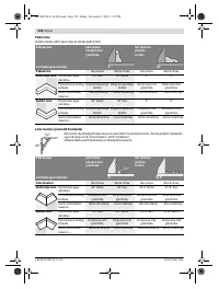
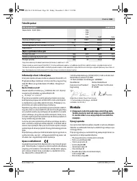
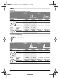
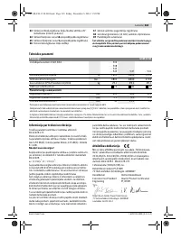
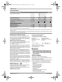
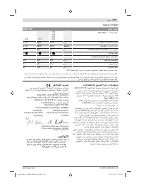
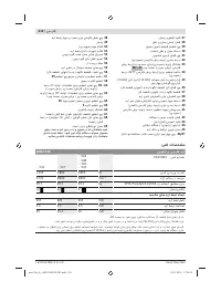
- 235 Технические данные; Применяйте средства защиты органов слуха!; Заявление о соответствии; Сборка; Комплект поставки; Панельная пила; Размеры пильных дисков
- 236 Стационарный или временный монтаж; Монтаж на верстаке производства Bosch; Отсос пыли и стружки; Внешняя система пылеотсоса
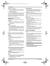
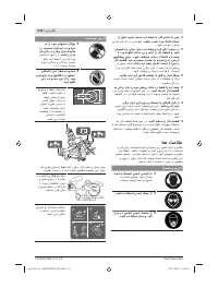
- 237 Демонтаж пильного диска; Работа с инструментом; Подготовка к эксплуатации
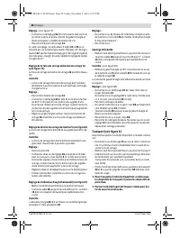
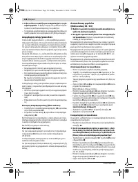
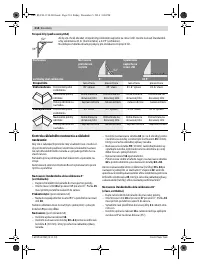
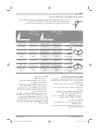
- 238 Настройка горизонтального угла распила; угол распила
- 239 Включение электроинструмента; Угол распила
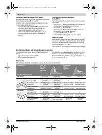
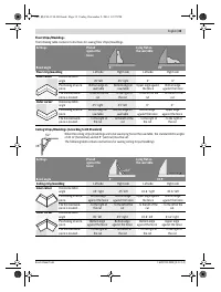
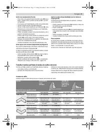
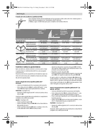
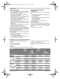
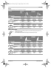
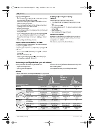
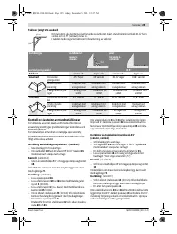
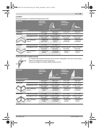
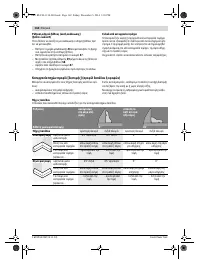
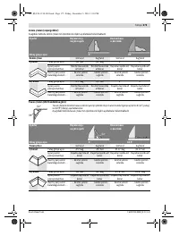
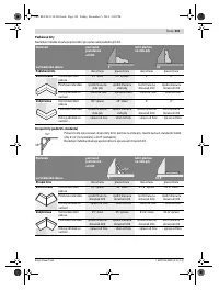
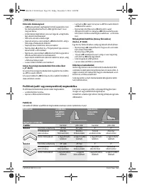
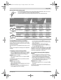
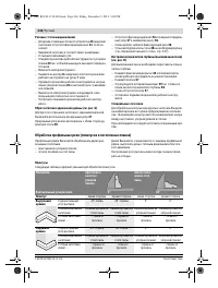
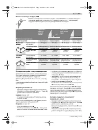
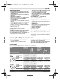
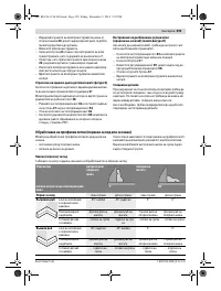
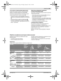
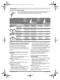
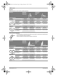
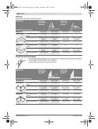
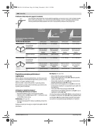
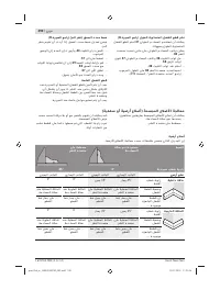
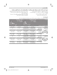
- 240 Резание с тяговым движением; Обработка профильных реек (плинтусов и потолочных планок); Плинтусы
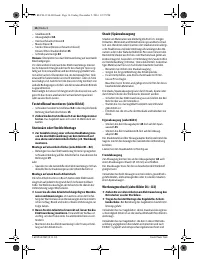
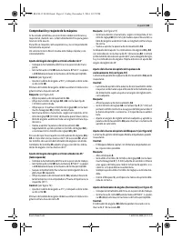
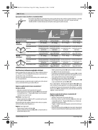
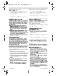
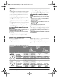
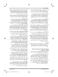
- 241 Основные настройки – контроль и коррекция; Настройка угла наклона в 0 °
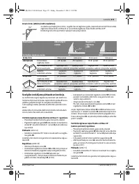
- 242 Настройка упорной планки
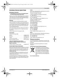
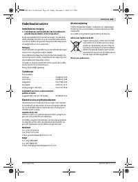
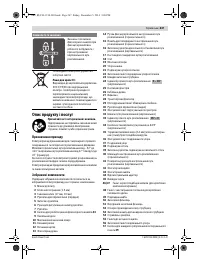
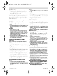
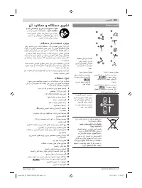
- 243 Техобслуживание и сервис; Техобслуживание и очистка; Очистка; Принадлежности; Россия; Беларусь; Утилизация


