
Пилы торцовочные Bosch 0.601.B19.100 - инструкция пользователя по применению, эксплуатации и установке на русском языке. Мы надеемся, она поможет вам решить возникшие у вас вопросы при эксплуатации техники.
Если остались вопросы, задайте их в комментариях после инструкции.
"Загружаем инструкцию", означает, что нужно подождать пока файл загрузится и можно будет его читать онлайн. Некоторые инструкции очень большие и время их появления зависит от вашей скорости интернета.


30
| English
1 609 92A 04K | (31.10.12)
Bosch Power Tools
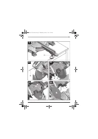
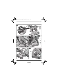
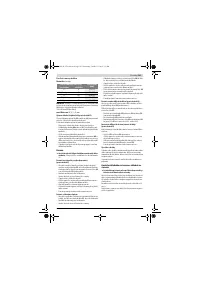
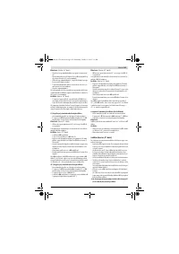
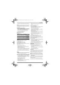
Position of the Operator (see figure N)
Do not stand in a line with the saw blade in front of the
machine. Always stand aside of the saw blade.
This pro-
tects your body against possible kickback.
– Keep hands, fingers and arms away from the rotating saw
blade.
– Do not cross your arms when operating the tool arm.
Permissible Workpiece Dimensions
Maximal
workpiece sizes:
Minimal
workpiece sizes (= all workpieces that can be
clamped left or right from the saw blade with the supplied ma-
terial clamp
29
):100 x 40 mm (length x width)
Cutting depth, max.
(0 ° /0 ° ): 70 mm
Replacing Insert Plates (see figure O)
The red insert plates
18
can become worn after prolonged
use of the machine.
Replace defective insert plates.
– Bring the power tool into the working position.
– Unscrew the screws
49
with an Allen key (size 4 mm) and
remove the old insert plates.
– Insert the new right-hand insert plate.
– Screw the insert plate as far as possible to the right with
the screws
49
so that the saw blade does not come into
contact with the insert plate over the complete length of
the possible slide motion.
– Repeat the work steps in the same manner for the left-hand
insert plate.
Sawing
Always tighten the locking knob 20 firmly before saw-
ing.
Otherwise the saw blade can become wedged in the
workpiece.
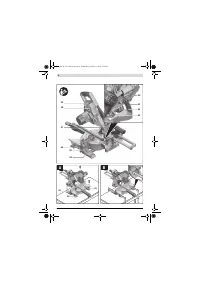
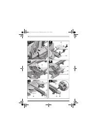
Sawing without Slide Movement (Cutting Off)
(see figure P)
– For cuts without slide movement (small workpieces), loos-
en the locking screw
33
in case it is tightened. Slide the
tool arm to the stop in the direction of the fence
14
and
retighten the locking screw
33
.
– Set the desired mitre angle.
– Firmly clamp the workpiece as appropriate for its dimen-
sions.
– Switch on the machine.
– Press locking switch
9
and slowly guide the tool arm down-
ward by the handle
8
.
– Saw through the workpiece applying uniform feed.
– Switch off the machine and wait until the saw blade has
come to a complete stop.
– Guide the tool arm slowly upward.
Sawing with Slide Movement
– For cuts using the slide device
1
(wide workpieces), loosen
the locking screw
33
in case it is tightened.
– Set the desired mitre angle.
– Firmly clamp the workpiece as appropriate for its dimen-
sions.
– Pull the tool arm away from the fence
14
far enough so that
the saw blade is in front of the workpiece.
– Switch on the machine.
– Press locking switch
9
and slowly guide the tool arm down-
ward by the handle
8
.
– Press the tool arm in the direction of the fence
14
and saw
through the workpiece applying uniform feed.
– Switch off the machine and wait until the saw blade has
come to a complete stop.
– Guide the tool arm slowly upward.
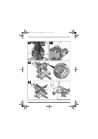
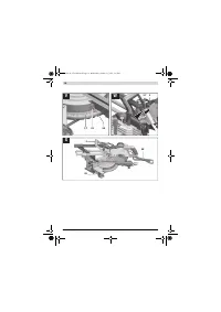
Sawing Workpieces of the Same Length (see figure Q)
The material stop
36
(accessory) can be used for easily saw-
ing workpieces to the same length.
The material stop can be mounted on either side of the saw ta-
ble extension
13
.
– Loosen lock screw
50
and swing the material stop
36
over
clamping screw
51
.
– Retighten lock screw
50
.
– Adjust the saw table extension
13
to the desired length
(see “Extending the Saw Table”, page 28).
Adjusting the Depth Stop (Sawing Grooves) (see figure R)
The depth stop must be adjusted when a trench gap is to be
sawed.
– Swivel the depth stop
32
outward.
– Press locking lever
9
and tilt the tool arm to the desired po-
sition.
– Turn adjusting screw
4
, until the screw end touches depth
stop
32
.
– Guide the tool arm slowly upward.
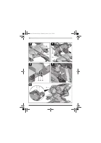
Special Workpieces
When sawing curved or round workpieces, these must be es-
pecially secured against slipping. At the cutting line, no gap
may exist between workpiece, fence and saw table.
Provide for special fixtures, if required.
Checking and Adjusting the Basic Adjustment
Before any work on the machine itself, pull the mains
plug.
To ensure precise cuts, the basic adjustment of the machine
must be checked and adjusted as necessary after intensive
use.
A certain level of experience and appropriate specialty tools
are required for this.
A Bosch after-sales service station will handle this mainte-
nance task quickly and reliably.
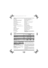
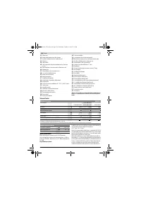
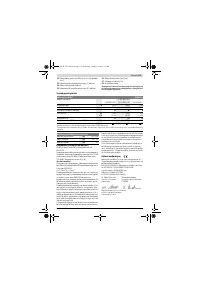
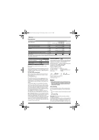
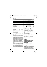
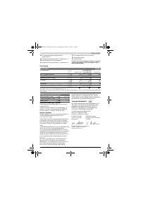
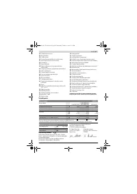
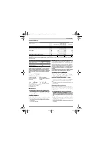
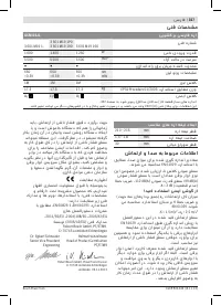
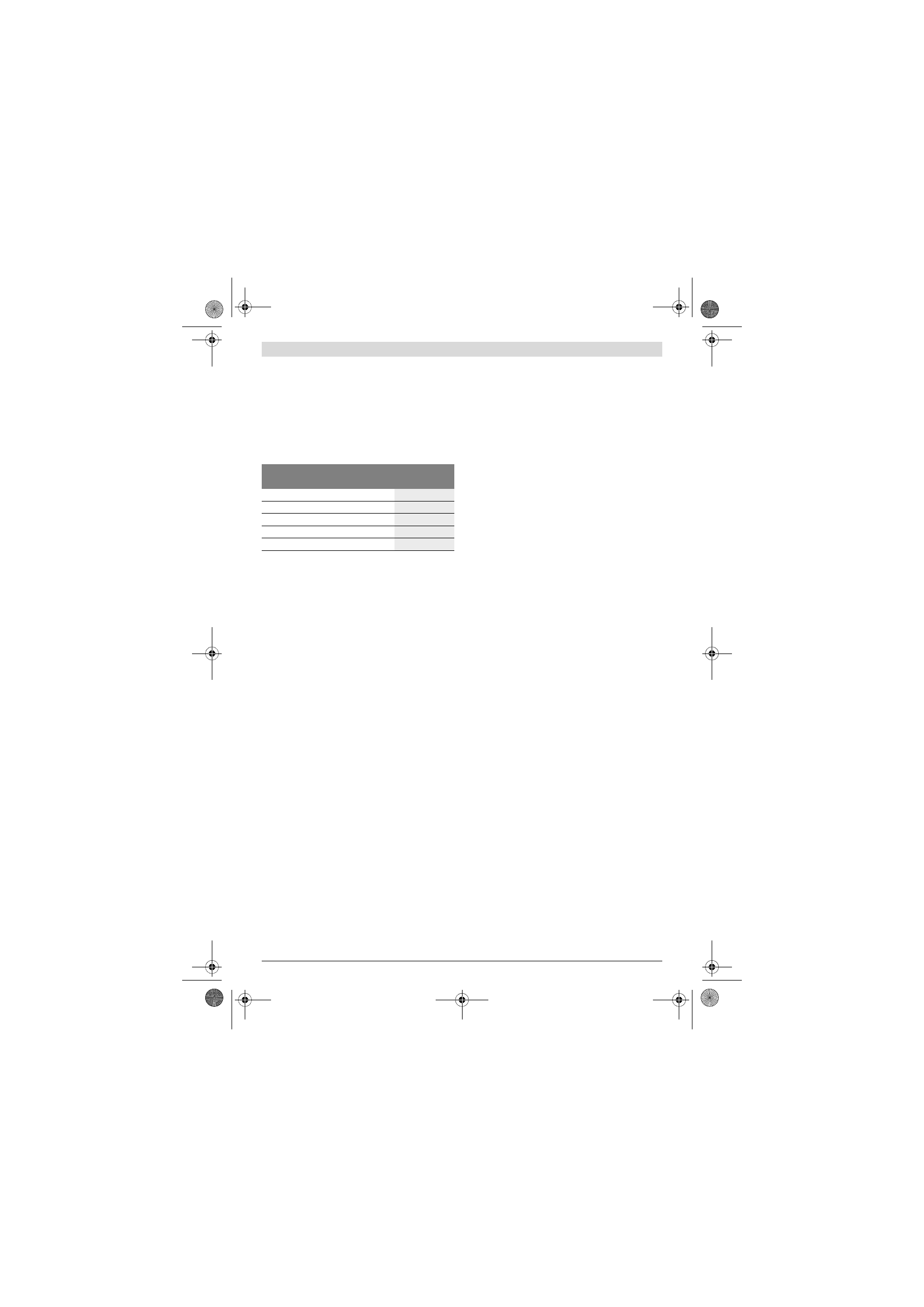
Mitre/Bevel Angle
Height x Width
[mm]
Horizontal
Vertical
0 °
0 °
70 x 312
45 ° (leftward/rightward)
0 °
70 x 225
0 °
45 °
45 x 312
45 ° (leftward)
45 °
45 x 225
45 ° (rightward)
45 °
45 x 225
OBJ_BUCH-1736-002.book Page 30 Wednesday, October 31, 2012 3:55 PM
Содержание
- 198 Применение электроинструмента и обращение с ним
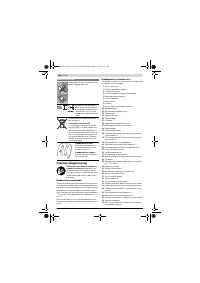
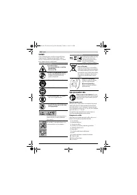
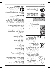
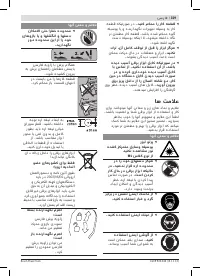
- 199 Закрепляйте заготовку.; Символы; Символы и их значение
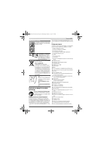
- 200 Описание продукта и услуг; Применение по назначению; Зажимной рычаг зажат:
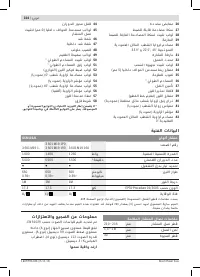
- 201 Технические данные; Применяйте средства защиты органов слуха!; Заявление о соответствии; Панельная пила; Размеры пильных дисков
- 202 Сборка; Комплект поставки; Монтаж на верстаке производства Bosch; Отсос пыли и стружки; Избегайте скопления пыли на рабочем месте.
- 203 Демонтаж пильного диска; Работа с инструментом; Подготовка к эксплуатации; Угол распила
- 204 Настройка горизонтального угла распила; слева
- 205 Указания по применению; Общие указания для пиления; Пиление; Резание с тяговым движением
- 206 Специальные заготовки; Основные настройки; Настройка угла наклона в 0
- 207 Техобслуживание и сервис; Техобслуживание и очистка; Очистка; Принадлежности; Товарный No
- 208 Россия; Утилизация
Характеристики

Остались вопросы?Не нашли свой ответ в руководстве или возникли другие проблемы? Задайте свой вопрос в форме ниже с подробным описанием вашей ситуации, чтобы другие люди и специалисты смогли дать на него ответ. Если вы знаете как решить проблему другого человека, пожалуйста, подскажите ему :)


