
Котел De Dietrich MS 24 BIC - инструкция пользователя по применению, эксплуатации и установке на русском языке. Мы надеемся, она поможет вам решить возникшие у вас вопросы при эксплуатации техники.
Если остались вопросы, задайте их в комментариях после инструкции.
"Загружаем инструкцию", означает, что нужно подождать пока файл загрузится и можно будет его читать онлайн. Некоторые инструкции очень большие и время их появления зависит от вашей скорости интернета.


68
71.06199.02 - EN
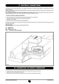
INSTALLATION INSTRUCTIONS
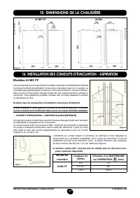
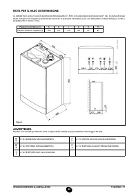
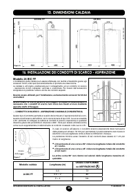
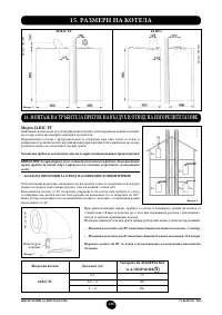
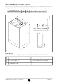
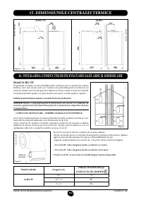
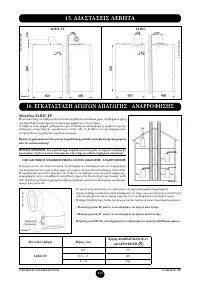
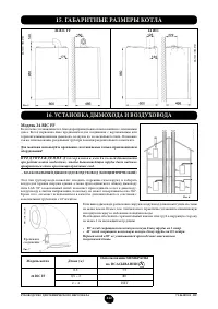
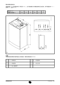
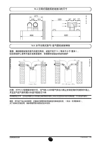
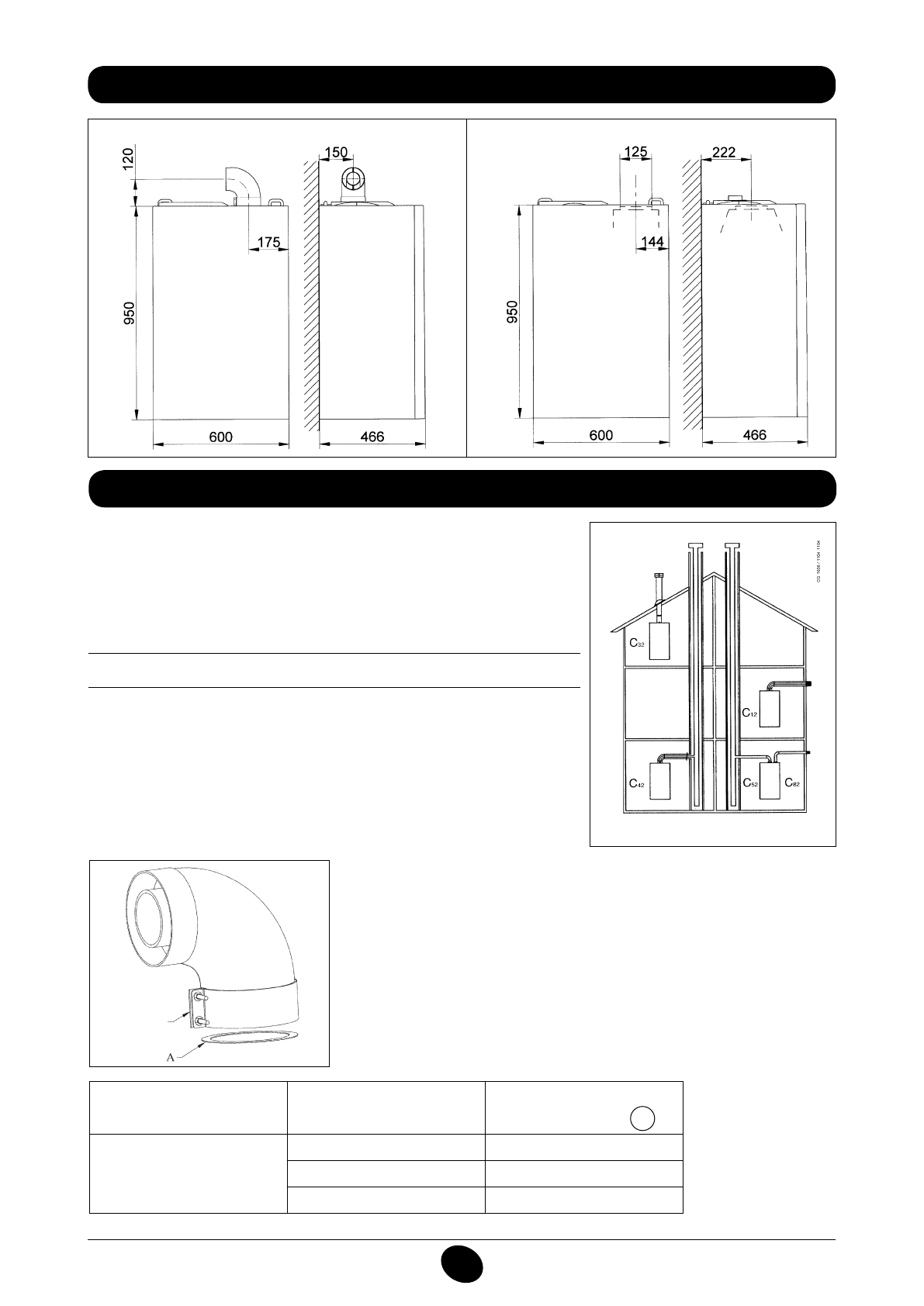
14. DIMENSIONI CALDAIA
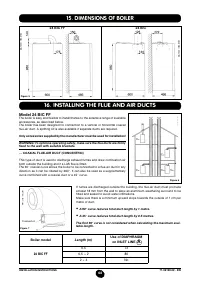
15. DIMENSIONS OF BOILER
Figure 5
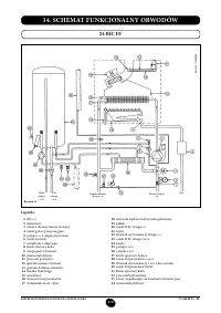
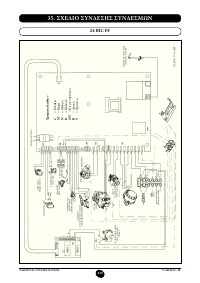
24 BIC FF
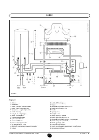
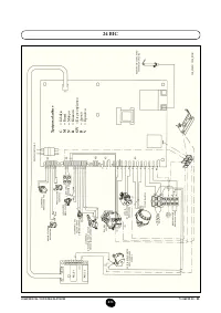
24 BIC
CG_1848 / 1104_0702
CG_1848 / 1104_0703
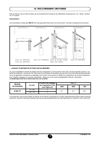
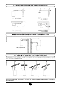
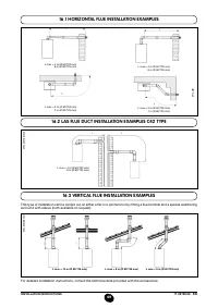
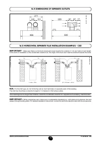
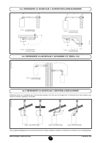
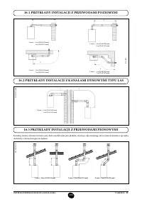
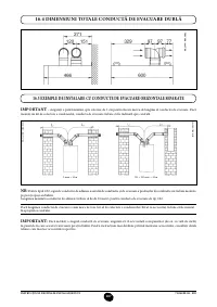
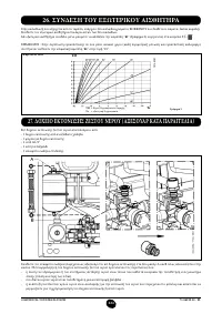
16. INSTALLING THE FLUE AND AIR DUCTS
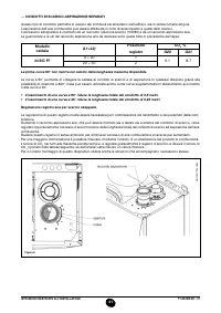
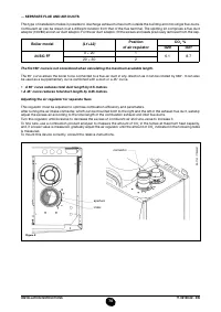
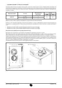
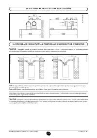
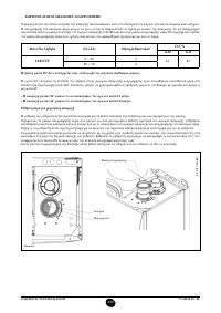
Boiler model
Length (m)
Use of DIAPHRAGM
on INLET LINE
A
24 BIC FF
0,5
73
0,5 ÷ 2
80
2 ÷ 4
No
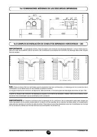
If fumes are discharged outside the building, the lue-air duct must protrude
at least 18 mm from the wall to allow an aluminium weathering surround to be
itted and sealed to avoid water iniltrations.
Make sure there is a minimum upward slope towards the outside of 1 cm per
metre of duct.
•
A 90° curve reduces total duct length by 1 metre.
•
A 45° curve reduces total duct length by 0.5 metres.
The first 90° curve is not considered when calculating the maximum avai-
lable length.
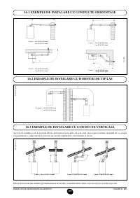
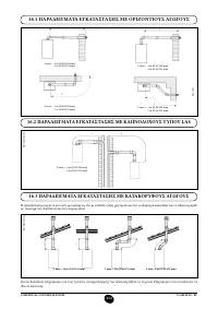
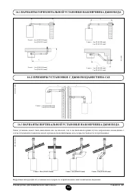
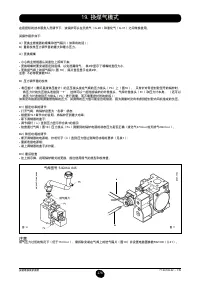
Figure 7
Connector
0805_2901 / C
G_2073
Model 24 BIC FF
The boiler is easy and lexible to install thanks to the extensive range of available
accessories, as described below.
The boiler has been designed for connection to a vertical or horizontal coaxial
lue-air duct. A splitting kit is also available if separate ducts are required.
Only accessories supplied by the manufacturer must be used for installation!
WARNING: To optimise operating safety, make sure the flue ducts are firmly
fixed to the wall with suitable brackets.
… COAXIAL FLUE-AIR DUCT (CONCENTRIC)
This type of duct is used to discharge exhaust fumes and draw combustion air
both outside the building and if a LAS lue is itted.
The 90° coaxial curve allows the boiler to be connected to a lue-air duct in any
direction as it can be rotated by 360°. It can also be used as a supplementary
curve combined with a coaxial duct or a 45° curve.
Figure 6
Содержание
- 234 Уважае; СОДЕРЖАНИЕ; РУКОВОДСТВО ДЛЯ ПОЛЬЗОВАТЕЛЯ
- 235 ПОДГОТОВКА К УСТАНОВКЕ; ПОДГОТОВКА К ПЕРВОМУ ПУСКУ
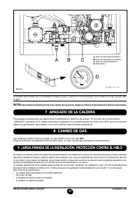
- 236 Внимание
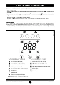
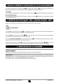
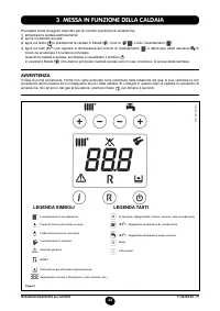
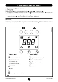
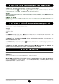
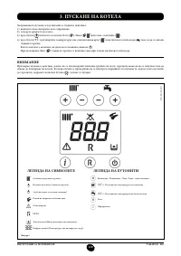
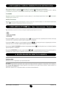
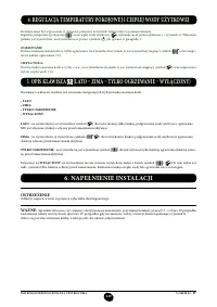
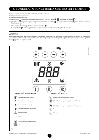
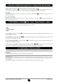
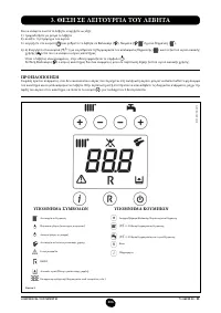
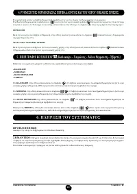
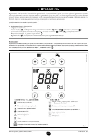
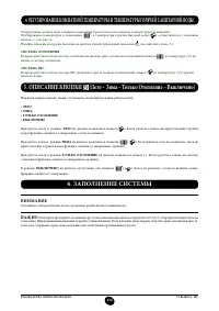
- 237 ОПИСАНИЕ КНОПКИ (Лето – Зима – Только Отопление – Выключено); ЗАПОЛНЕНИЕ СИСТЕМЫ
- 238 ВЫКЛЮЧЕНИЕ КОТЛА; ВЫКЛЮЧЕНИЕ НА ДЛИТЕЛЬНЫЙ ПЕРИОД. ЗАЩИТА ОТ ЗАМЕРЗАНИЯ
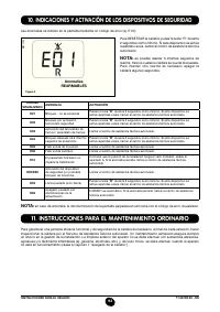
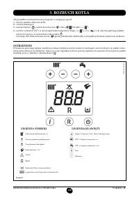
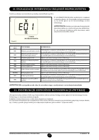
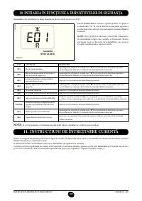
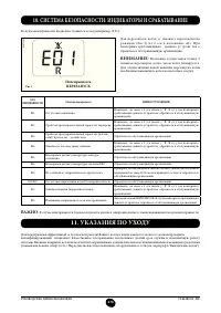
- 239 СИСТЕМА БЕЗОПАСНОСТИ: ИНДИКАТОРЫ И СРАБАТЫВАНИЕ; Неисправность
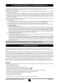
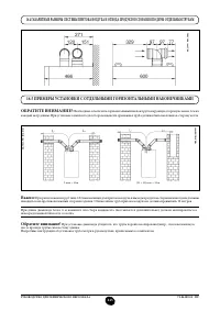
- 241 ПРОВЕРКИ ПЕРЕД УСТАНОВКОЙ КОТЛА
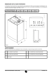
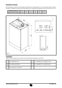
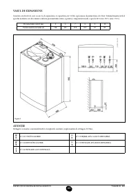
- 242 ПРИМЕЧАНИЕ ПО РАСШИРИТЕЛЬНОМУ БАКУ
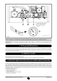
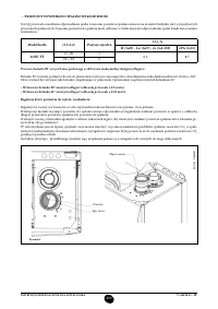
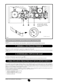
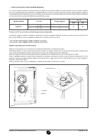
- 243 Модель 24 BIC FF; Модель котла; НЕТ
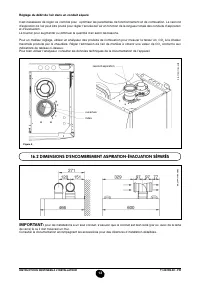
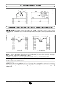
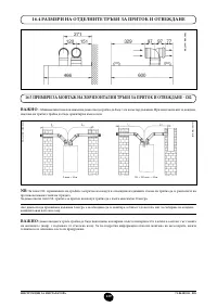
- 244 ВАРИАНТЫ ГОРИЗОНТАЛЬНОЙ УСТАНОВКИ НАКОНЕЧНИКА ДЫМОХОДА
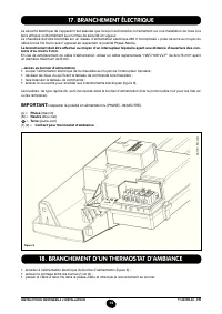
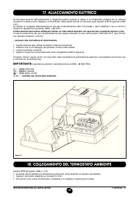
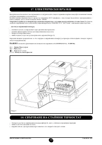
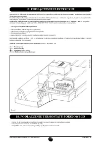
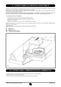
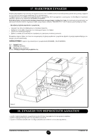
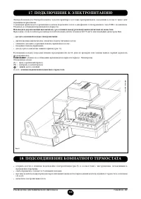
- 247 ПОДКЛЮЧЕНИЕ К ЭЛЕКТРОПИТАНИЮ; ПОДСОЕДИНЕНИЕ КОМНАТНОГО ТЕРМОСТАТА
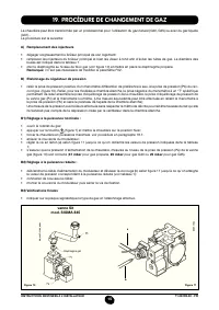
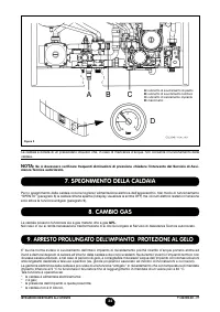
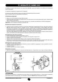
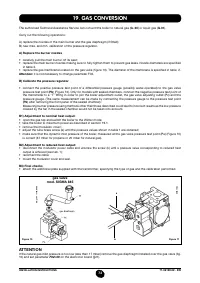
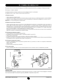
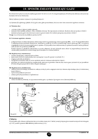
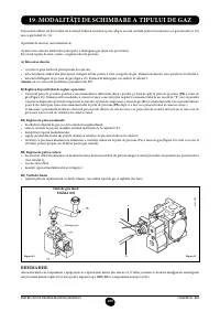
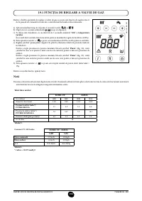
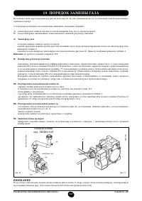
- 248 ПОРЯДОК ЗАМЕНЫ ГАЗА; газовый клапан
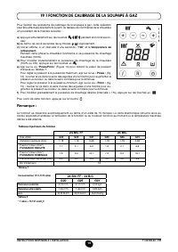
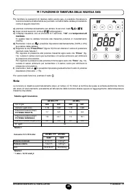
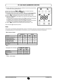
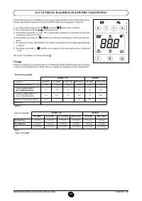
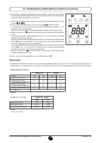
- 249 ФУНКЦИЯ КАЛИБРОВКИ ГАЗОВОГО КЛАПАНА; Примечание
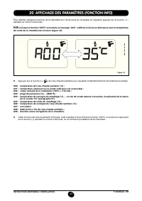
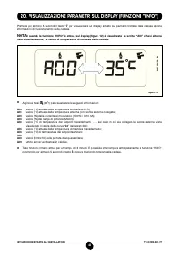
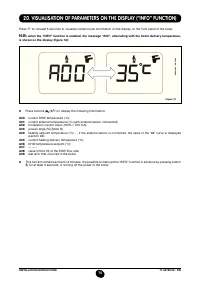
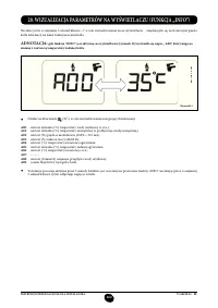
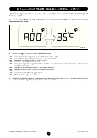
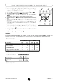
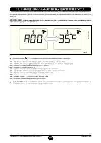
- 250 ВЫВОД ИНФОРМАЦИИ НА ДИСПЛЕЙ КОТЛА
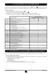
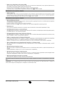
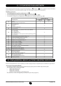
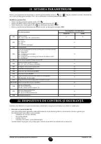
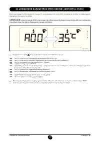
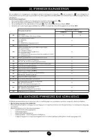
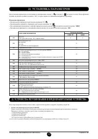
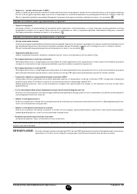
- 251 УСТАНОВКА ПАРАМЕТРОВ; УСТРОЙСТВА РЕГУЛИРОВАНИЯ И ПРЕДОХРАНИТЕЛЬНЫЕ УСТРОЙСТВА
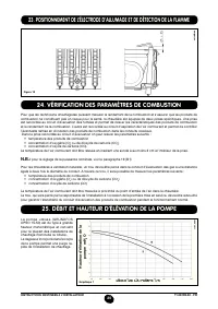
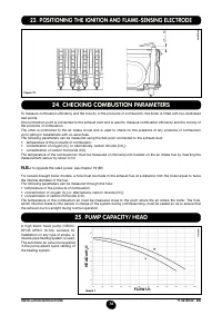
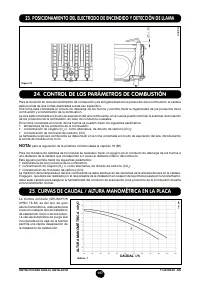
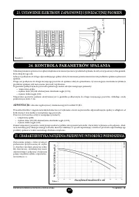
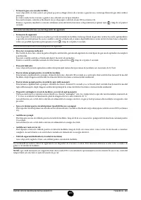
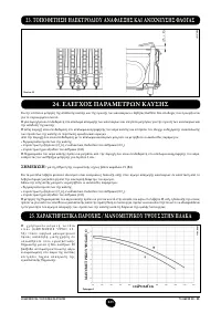
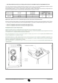
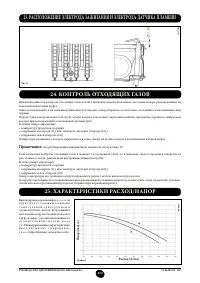
- 253 КОНТРОЛЬ ОТХОДЯЩИХ ГАЗОВ; ап
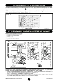
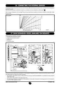
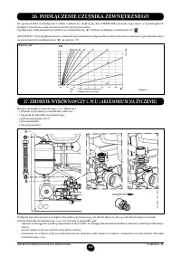
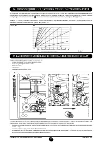
- 254 ПРИСОЕДИНЕНИЕ ДАТЧИКА УЛИЧНОЙ ТЕМПЕРАТУРЫ
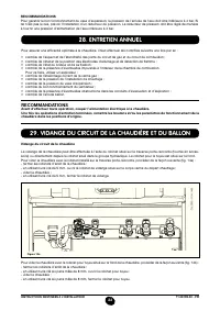
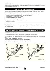
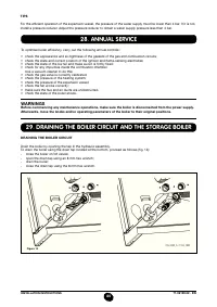
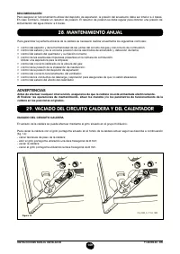
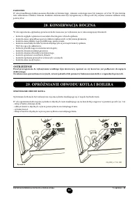
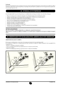
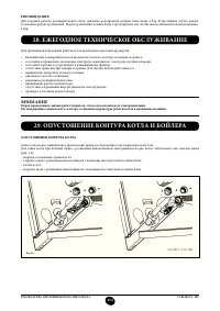
- 255 ЕЖЕГОДНОЕ ТЕХНИЧЕСКОЕ ОБСЛУЖИВАНИЕ; ОПУСТОШЕНИЕ КОНТУРА КОТЛА И БОЙЛЕРА
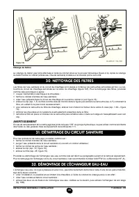
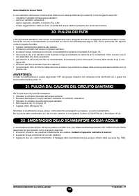
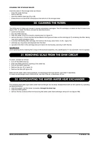
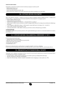
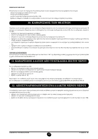
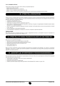
- 256 ОЧИСТКА ОТ ИЗВЕСТКОВОГО НАЛЕТА В СИСТЕМЕ ГВС
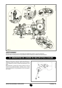
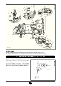
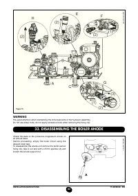
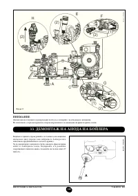
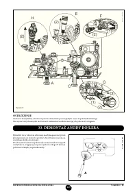
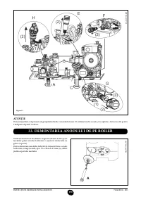
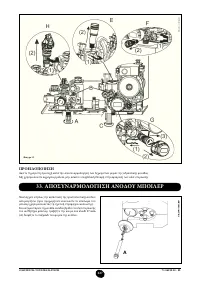
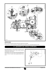
- 257 ДЕМОНТАЖ АНОДА БОЙЛЕРА
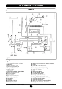
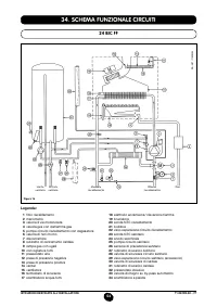
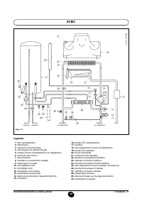
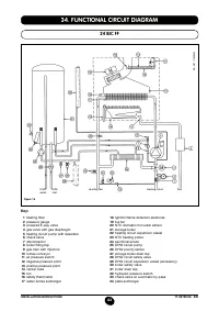
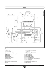
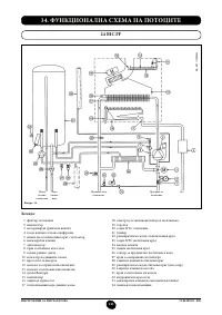
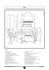
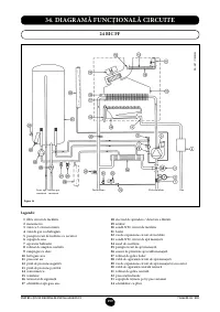
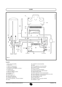
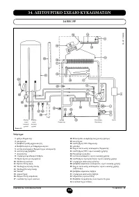
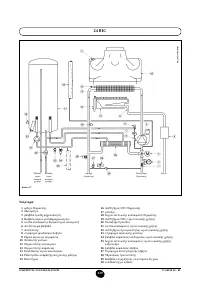
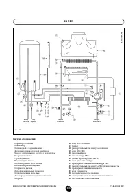
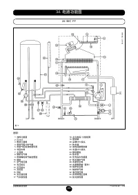
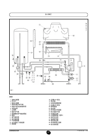
- 258 ФУНКЦИОНАЛЬНАЯ СХЕМА КОНТУРОВ
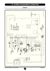
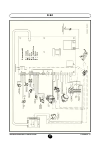
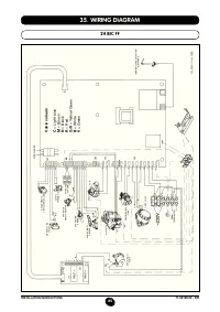
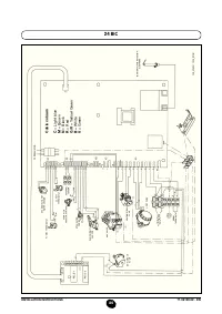
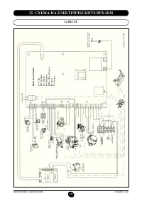
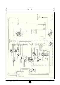
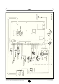
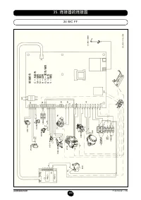
- 260 СХЕМЫ ЭЛЕКТРИЧЕСКИХ СОЕДИНЕНИЙ; Цв
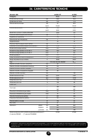
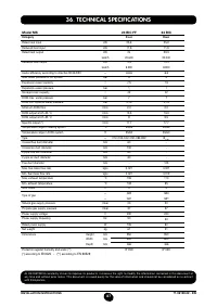
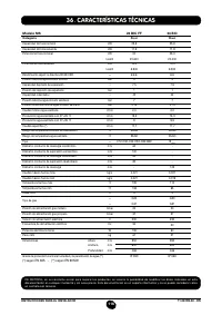
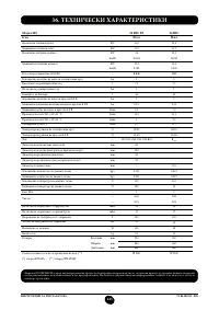
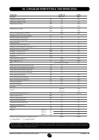
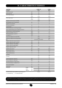
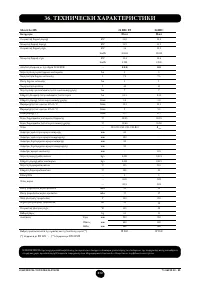
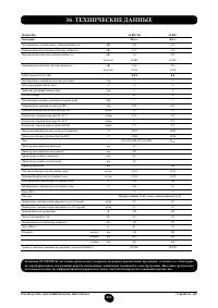
- 262 ТЕХНИЧЕСКИЕ ДАННЫЕ


