
Обогреватели Wing W200 EC 1-4-2801-0057 - инструкция пользователя по применению, эксплуатации и установке на русском языке. Мы надеемся, она поможет вам решить возникшие у вас вопросы при эксплуатации техники.
Если остались вопросы, задайте их в комментариях после инструкции.
"Загружаем инструкцию", означает, что нужно подождать пока файл загрузится и можно будет его читать онлайн. Некоторые инструкции очень большие и время их появления зависит от вашей скорости интернета.


29
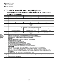
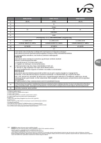
8
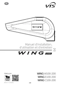
EN
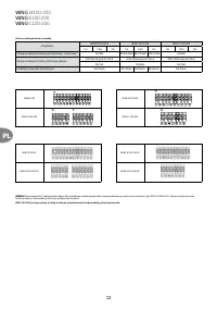
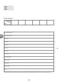
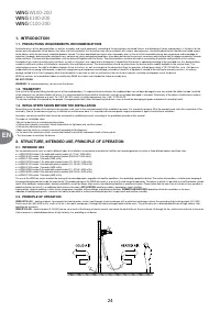
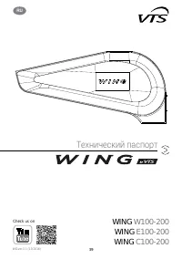
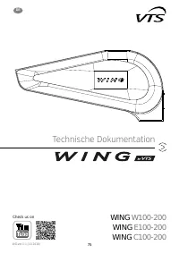
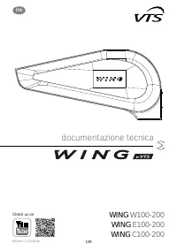
WING
W100-200
WING
E100-200
WING
C100-200
1
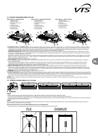
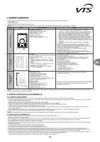
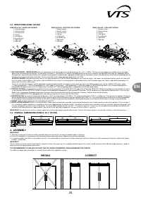
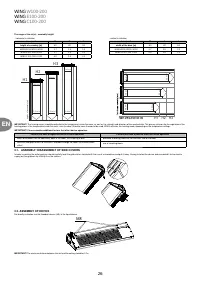
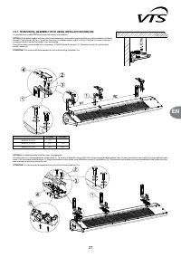
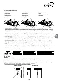
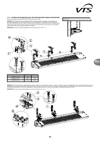
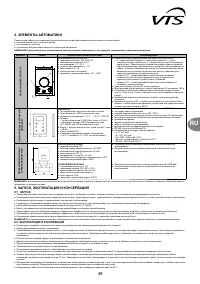
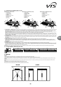
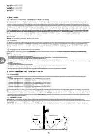
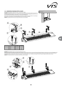
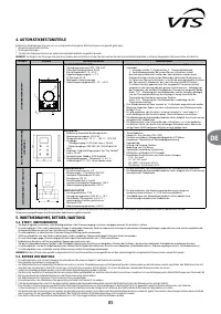
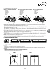
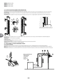
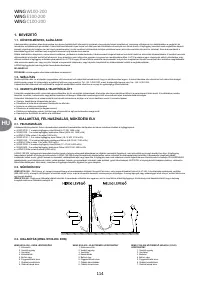
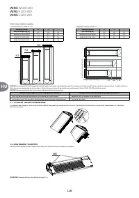
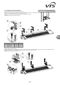
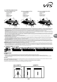
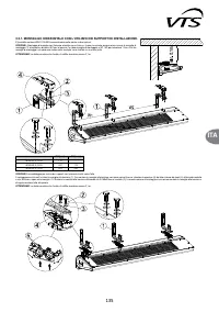
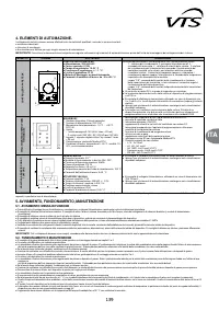
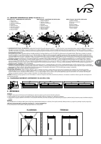
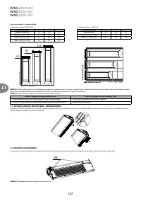
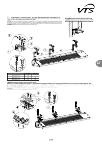
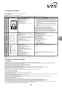
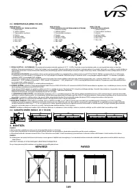
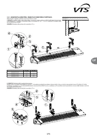
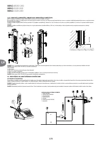
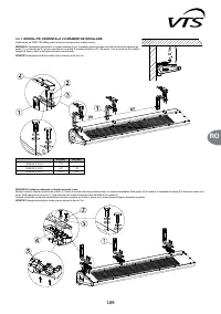
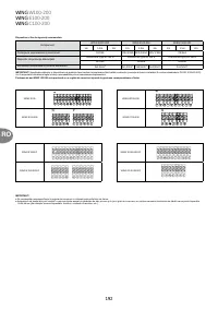
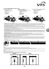
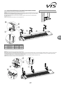
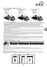
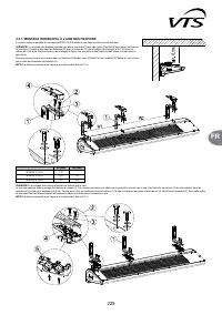
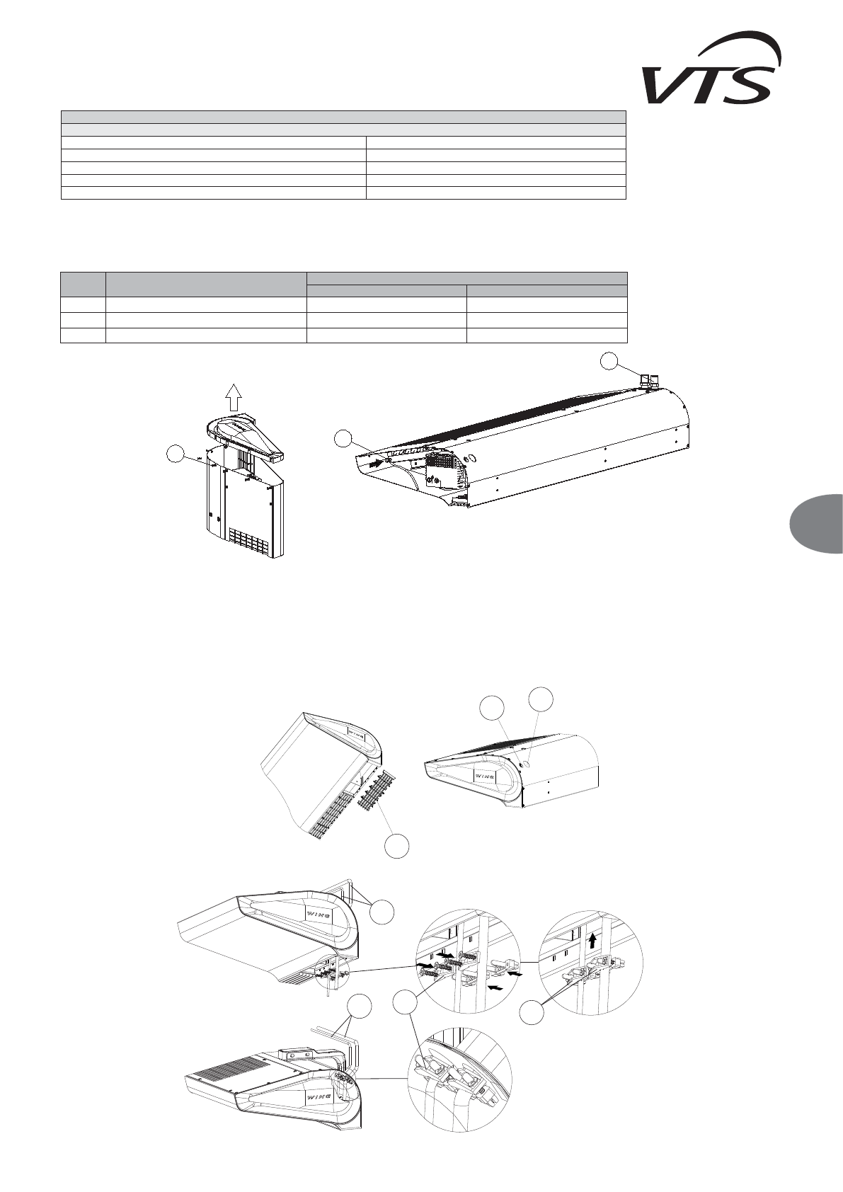
3.2.2. VERTICAL ASSEMBLY WITH USING INSTALATION HANDLES.
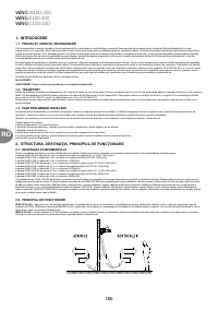
It is possible to assemble WING to a wall vertically on both sides of the gate (with the motor on the bottom or on the top).
For this option it is not important if you screw the handles down to the unit first and then screw the whole down to the wall or first attach the handles to the wall and then screw the curtain down to the
handles.
To perform vertical assembly, use M8x70 (outside the scope of VTS delivery) screws. Screw 2 or 3 brackets using the screws, passing through flat washers (3), to the threaded sleeves mounted in the
upper part of the housing.
IMPORTANT:
In case of vertical assembly the minimal distance between the device and the floor (100mm) for access to the water coil blowdown connection and the cable terminal should be provide.
IMPORTANT!
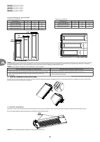
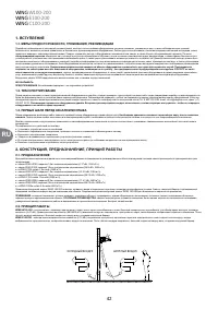
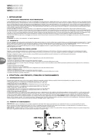
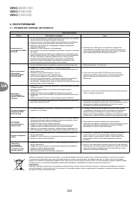
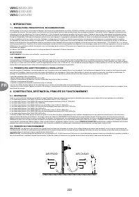
The device is intended for the operation in dry rooms, exclusively. Thus, pay particular attention to the condensation of water vapour on engine elements, since it is not fitted
for operating in humid environment.
IMPORTANT!
The WING air curtains are not intended for the installation:
●
Outdoors;
●
In humid rooms;
●
In rooms categorised as explosive environments;
●
In rooms with very high levels of dustiness;
●
In rooms with aggressive atmosphere (due to the presence of copper and aluminium structural elements in the heat exchanger and electric heaters).
IMPORTANT!
The WING EH air curtains are not intended for the installation on suspended ceilings.
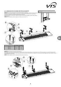
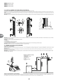
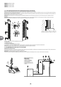
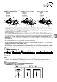
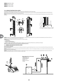
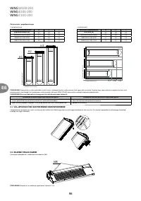
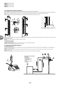
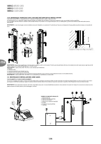
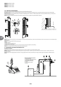
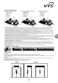
3.3. ASSEMBLY AND INSTALLATION GUIDELINES
CONNECTING OF HEATING MEDIUM
Protect the heat exchanger terminal against the impact of the torque moment 1, when installing a pipeline transporting a heating medium. The weight of installed pipelines should not impose a load on
the heater’s terminals.
IMPORTANT!
Pay particular attention to the leak-tightness of connections, when filing the hydraulic system. Make sure that the water flowing from a leaky connection does not leak to the
electric engine (at the vertical assembly)
IMPORTANT!
It is recommended to use filters in the hydraulic system. It is recommended to clean/rinse the system, draining a few litres of water, prior to the connecting of hydraulic conduits
(the supply conduits, in particular).
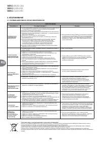
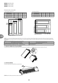
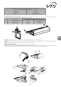
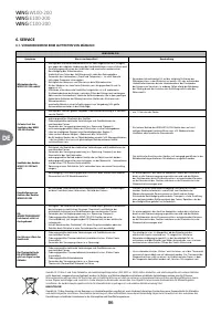
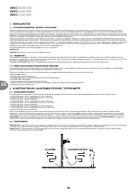
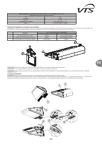
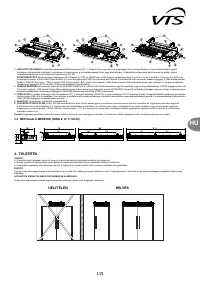
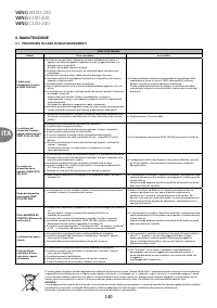
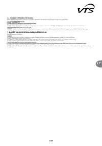
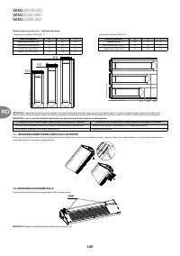
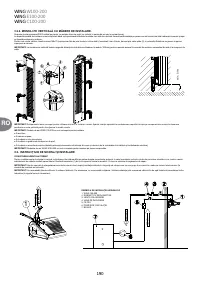
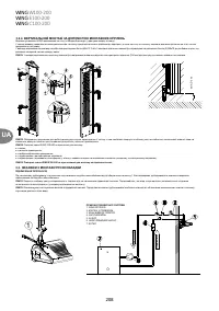
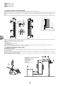
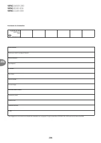
VENTING OF DEVICE/DRAINING OF HEATING MEDIUM
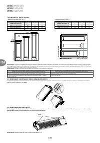
To perform horizontal and vertical assembly, the exchanger on the right-hand side of the door vents automatically. In the case of lateral assembly with the stub pipes facing downwards, to vent
the exchanger, remove the side cover. Unscrew the screws (1) around the cover and remove the cover. A valve with a hose is situated below the cover.
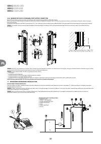
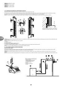
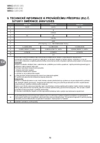
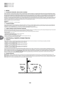
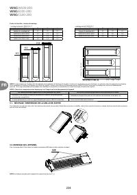
EXAMPLE OF HYDRAULIC SYSTEM
1. WING 100-200
2. VALVE WITH ACTUATOR
3. VENT VALVE
4. SHUT-OFF VALVE
5. FILTER
6. CIRCULATING PUMP
7. BOILER
SUPPL
Y
SUPPL
Y
RETURN
m
in
. 0
,1
m
RETURN
9
EN
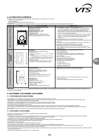
IMPORTANT!
While venting the exchanger you should pay special attention to securing the device against accidental penetration of water into electrical elements.
IMPORTANT!
Remember to vent the heater, if it has been activated after a prior draining of the heating medium.
IMPORTANT!
Pay particular attention to the leak-tightness of connections, when filing the hydraulic system. Make sure that the water flowing from a leaky connection does not leak to the
electric engine (at the vertical assembly).
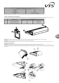
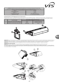
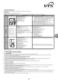
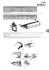
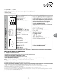
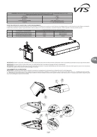
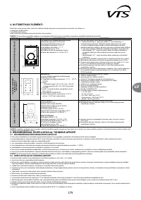
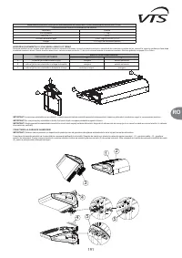
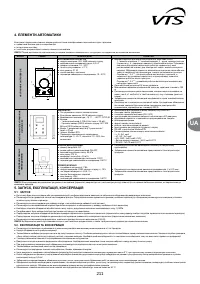
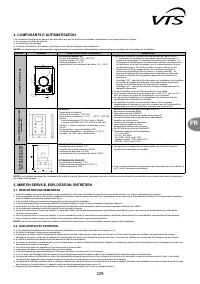
CONNECTING OF POWER SUPPLY
IMPORTANT!
The system must be equipped with protective equipment that guarantees the disconnecting of the device on all poles of the power source.
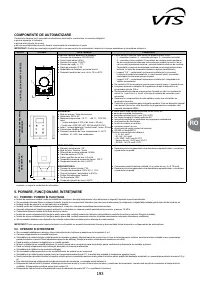
Connection to the electric system must be performed by a duly authorized and qualified person .Wire passes are located on the back side of the curtain : (1) – control wire packing , (2) – power
wire packing. The access to the terminal strip is obtained by means of removing the outlet grid (3) from the motor's side. It is required to mount the cable strain relief (5), to protect the cable (4)
against pulling.
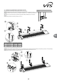
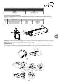
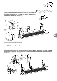
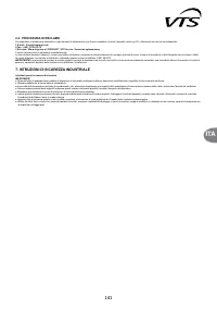
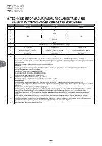
VENTING OF DEVICE/DRAINING OF HEATING MEDIUM
Ventin of the curtain water coil followed by loosening the union connection on the outlet connection. In case of the vertical assembly with the coils connection on the bottom side, the acces to
the vent valve is by removing the side cover. To do it one should remove the screws (1) around the cover and remove the cover. There is a valve (2) with a hose.
1
2
3
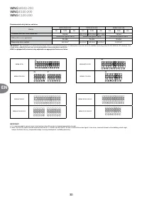
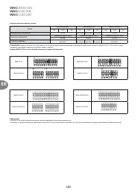
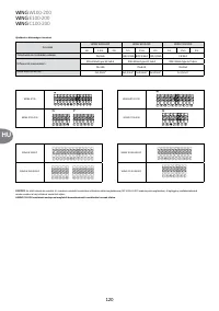
WORKING POSITION
VENT/DRAIN MARKING
2
3
A
horizontal (downward air feed)
drain
automatic venting
B
vertical (air feed from left to right)
drain
automatic venting
C
vertical (air feed from right to left
venting
drain
1
2
3
4
4
5
5
9
PL
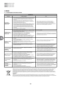
ODPOWIETRZENIE URZĄDZENIA/ SPUST CZYNNIKA GRZEWCZEGO
W przypadku montażu poziomego i pionowego po prawej stronie drzwi wymiennik odpowietrza się sam. W przypadku montażu bocznego z króćami do dołu, aby odpowietrzyć wymiennik
należy zdjąć pokrywę boczną. W tym celu wykręcić wkręty (1) dookoła pokrywy i wyjąć pokrywę. Pod pokrywą znajduje się zaworek z wężykiem.
1
2
3
UWAGA!
Podczas odpowietrzania wymiennika należy zwrócić szczególną uwagę na zabezpieczenie urządzenia przed przypadkowym przedostaniem się wody do elementów elektrycznych.
UWAGA!
W trakcie napełniania instalacji hydraulicznej należy zwrócić szczególną uwagę na szczelność podłączeń. Istotne jest, aby woda z nieszczelnego podłączenia nie przedostała się do
silnika elektrycznego (przy montażu pionowym).
UWAGA!
W przypadku uruchomienia urządzenia po wcześniejszym spuszczeniu czynnika grzewczego należy pamiętać o odpowietrzeniu nagrzewnicy.
PODŁĄCZENIE ZASILANIA ELEKTRYCZNEGO
UWAGA!
Istnieje konieczność wyposażenia instalacji stałej w środki zapewniające odłączenie urządzenia na wszystkich biegunach źródła zasilania.
Podłączenia elektrycznego musi dokonać osoba posiadająca odpowiednie uprawnienia. Przepusty kablowe umieszczone są na tylnej ściance kurtyny: (1) – dławica przewodów sterowniczych,
(2) – dławica przewodów zasilających. Dostęp do listwy zaciskowej uzyskuje się poprzez zdemontowanie kratki wylotowej (3) od strony silnika. Na przewodzie (4) wymagane jest
zamontowanie odciążki kablowej (5) dla zabezpieczenia przewodu przed wyrwaniem.
POZYCJA PRACY
WOZNACZENIE ODPOWIETRZENIA/SPUSTU
2
3
A
pozioma (nadmuch z góry na dół)
spust
samoodpowietrzenie
B
pionowa (silnik na dole)
spust
samoodpowietrzenie
C
pionowa (silnik u góry)
odpowietrzenie
spust
1
2
3
4
4
5
5
9
PL
ODPOWIETRZENIE URZĄDZENIA/ SPUST CZYNNIKA GRZEWCZEGO
W przypadku montażu poziomego i pionowego po prawej stronie drzwi wymiennik odpowietrza się sam. W przypadku montażu bocznego z króćami do dołu, aby odpowietrzyć wymiennik
należy zdjąć pokrywę boczną. W tym celu wykręcić wkręty (1) dookoła pokrywy i wyjąć pokrywę. Pod pokrywą znajduje się zaworek z wężykiem.
1
2
3
UWAGA!
Podczas odpowietrzania wymiennika należy zwrócić szczególną uwagę na zabezpieczenie urządzenia przed przypadkowym przedostaniem się wody do elementów elektrycznych.
UWAGA!
W trakcie napełniania instalacji hydraulicznej należy zwrócić szczególną uwagę na szczelność podłączeń. Istotne jest, aby woda z nieszczelnego podłączenia nie przedostała się do
silnika elektrycznego (przy montażu pionowym).
UWAGA!
W przypadku uruchomienia urządzenia po wcześniejszym spuszczeniu czynnika grzewczego należy pamiętać o odpowietrzeniu nagrzewnicy.
PODŁĄCZENIE ZASILANIA ELEKTRYCZNEGO
UWAGA!
Istnieje konieczność wyposażenia instalacji stałej w środki zapewniające odłączenie urządzenia na wszystkich biegunach źródła zasilania.
Podłączenia elektrycznego musi dokonać osoba posiadająca odpowiednie uprawnienia. Przepusty kablowe umieszczone są na tylnej ściance kurtyny: (1) – dławica przewodów sterowniczych,
(2) – dławica przewodów zasilających. Dostęp do listwy zaciskowej uzyskuje się poprzez zdemontowanie kratki wylotowej (3) od strony silnika. Na przewodzie (4) wymagane jest
zamontowanie odciążki kablowej (5) dla zabezpieczenia przewodu przed wyrwaniem.
POZYCJA PRACY
WOZNACZENIE ODPOWIETRZENIA/SPUSTU
2
3
A
pozioma (nadmuch z góry na dół)
spust
samoodpowietrzenie
B
pionowa (silnik na dole)
spust
samoodpowietrzenie
C
pionowa (silnik u góry)
odpowietrzenie
spust
1
2
3
4
4
5
5
9
EN
IMPORTANT!
While venting the exchanger you should pay special attention to securing the device against accidental penetration of water into electrical elements.
IMPORTANT!
Remember to vent the heater, if it has been activated after a prior draining of the heating medium.
IMPORTANT!
Pay particular attention to the leak-tightness of connections, when filing the hydraulic system. Make sure that the water flowing from a leaky connection does not leak to the
electric engine (at the vertical assembly).
CONNECTING OF POWER SUPPLY
IMPORTANT!
The system must be equipped with protective equipment that guarantees the disconnecting of the device on all poles of the power source.
Connection to the electric system must be performed by a duly authorized and qualified person .Wire passes are located on the back side of the curtain : (1) – control wire packing , (2) – power
wire packing. The access to the terminal strip is obtained by means of removing the outlet grid (3) from the motor's side. It is required to mount the cable strain relief (5), to protect the cable (4)
against pulling.
VENTING OF DEVICE/DRAINING OF HEATING MEDIUM
Ventin of the curtain water coil followed by loosening the union connection on the outlet connection. In case of the vertical assembly with the coils connection on the bottom side, the acces to
the vent valve is by removing the side cover. To do it one should remove the screws (1) around the cover and remove the cover. There is a valve (2) with a hose.
1
2
3
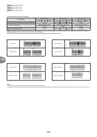
WORKING POSITION
VENT/DRAIN MARKING
2
3
A
horizontal (downward air feed)
drain
automatic venting
B
vertical (air feed from left to right)
drain
automatic venting
C
vertical (air feed from right to left
venting
drain
1
2
3
4
4
5
5
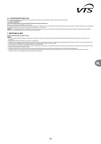
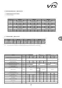
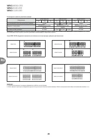
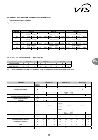
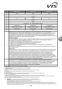
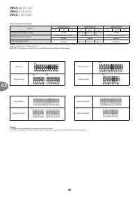
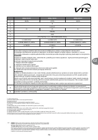
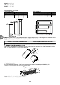
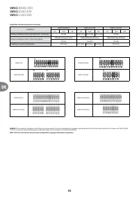
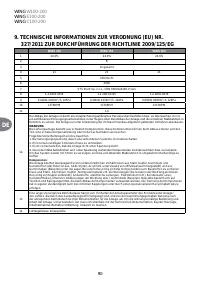
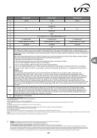
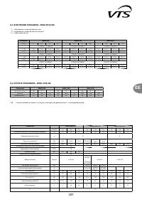
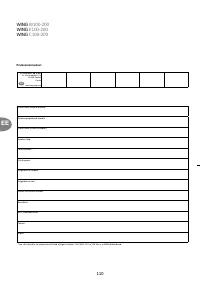
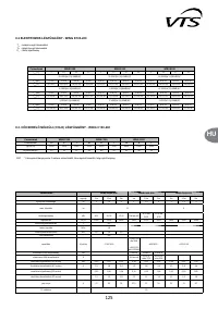
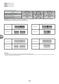
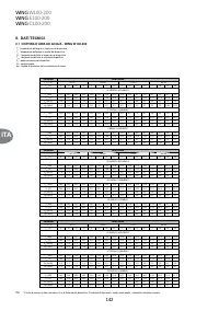
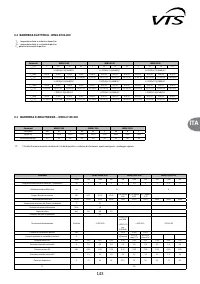
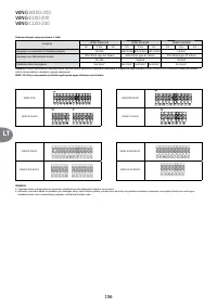
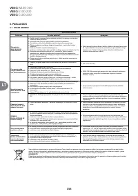
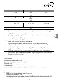
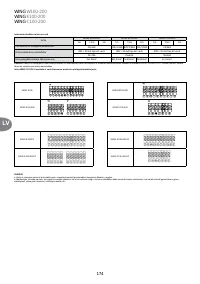
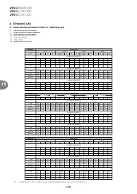
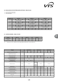
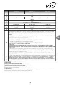
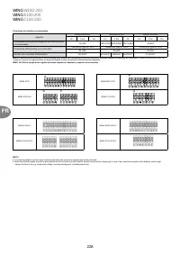
Note!
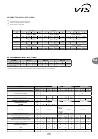
Maximum operating pressure of the medium for water coils is 16 bar, tested pressure: 21 bar
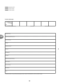
Requirements of the quality medium for the water coils:
Parameter
Value
Oil and grease
< 1 mg/l
pH at 25
o
C
8 to 9
Residual water hardness
[Ca2+, Mg2+]/[HCO3-] > 0.5
Oxygen
< 0.1 mg/l (as low as possible)


