Измерительные приборы Bosch GLL 2 - инструкция пользователя по применению, эксплуатации и установке на русском языке. Мы надеемся, она поможет вам решить возникшие у вас вопросы при эксплуатации техники.
Если остались вопросы, задайте их в комментариях после инструкции.
"Загружаем инструкцию", означает, что нужно подождать пока файл загрузится и можно будет его читать онлайн. Некоторые инструкции очень большие и время их появления зависит от вашей скорости интернета.


English |
15
Bosch Power Tools
1 609 92A 0KK | (7.5.14)
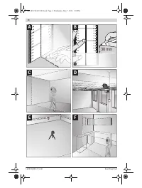
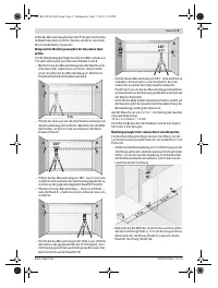
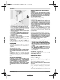
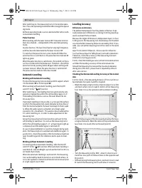
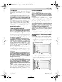
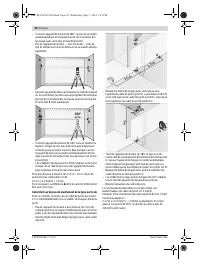
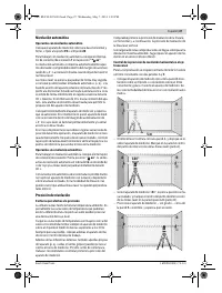
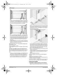
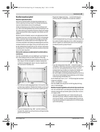
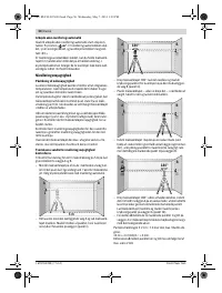
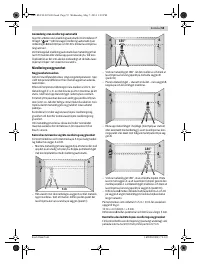
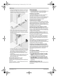
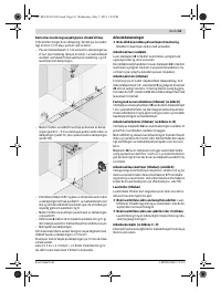
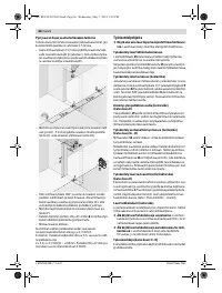
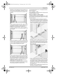
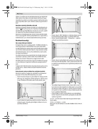
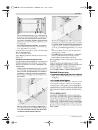
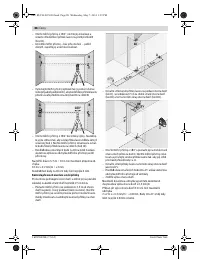
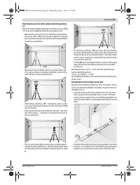
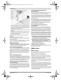
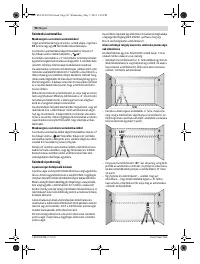
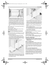
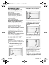
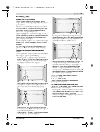
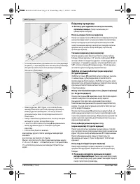
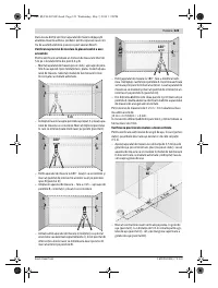
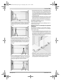
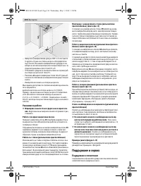
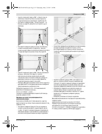
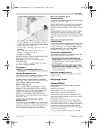
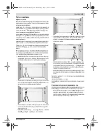
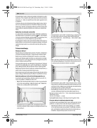
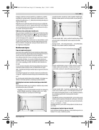
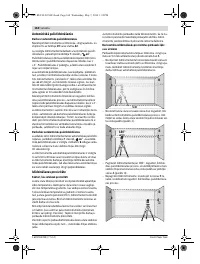
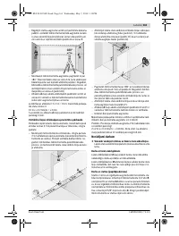
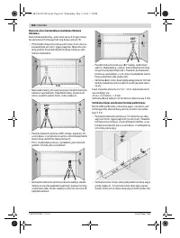
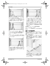
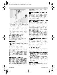
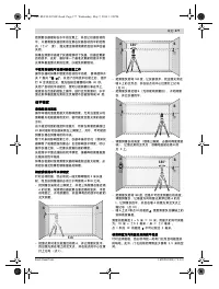
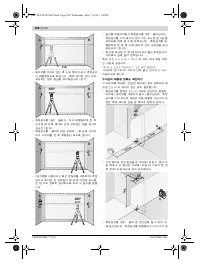
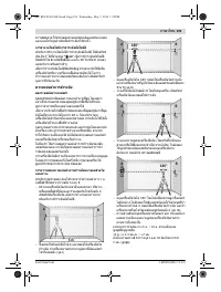
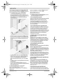
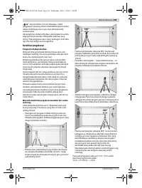
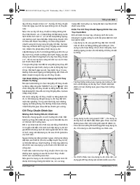
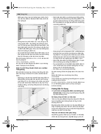
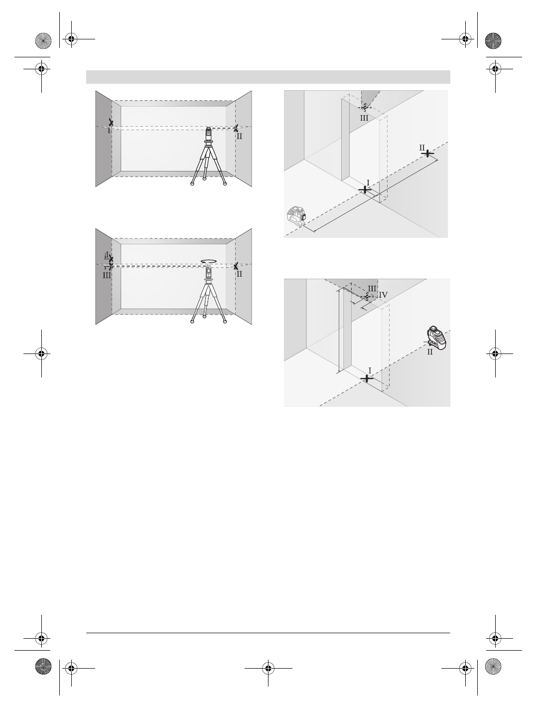
– Align the height of the measuring tool (using a tripod or by
underlaying, if required) in such a manner that the cross
point of the laser lines is projected against the previously
marked point
II
on the wall B.
– Without changing the height, turn around the measuring
tool by 180 °. Direct it against the wall A in such a manner
that the vertical laser line runs through the already marked
point
I
. Allow the measuring tool to level in and mark the
cross point of the laser lines on the wall A (point
III
).
– The difference
d
of both marked points
I
and
III
on wall A
results in the actual height deviation of the measuring tool
alongside the lateral axis.
On the measuring distance of 2 x 5 m = 10 m, the maximum
allowable deviation is:
10 m x ± 0.2 mm/m = ± 2 mm.
Thus, the difference
d
between points
I
and
III
must not ex-
ceed 2 mm (max.).
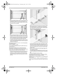
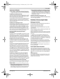
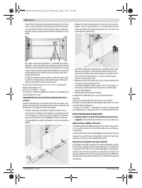
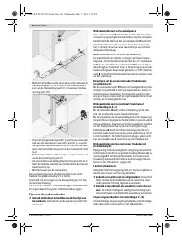
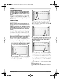
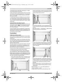
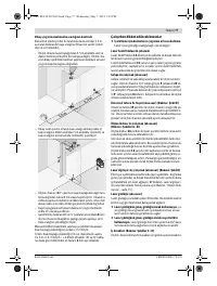
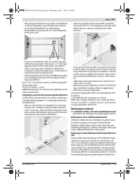
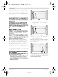
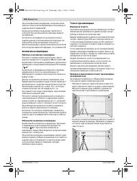
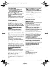
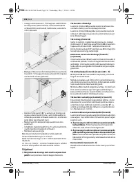
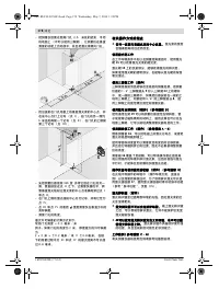
Checking the Levelling Accuracy of the Vertical Line
For this check, a door opening is required with at least 2.5 m
of space (on a firm surface) to each side of the door.
– Position the measuring tool on a firm, level surface (not on
a tripod) 2.5 m away from the door opening. Allow the
measuring tool to level in while in vertical operation with
automatic levelling, and direct the laser beam at the door
opening.
– Mark the centre of the vertical laser line at the floor of the
door opening (point
I
), at a distance of 5 m beyond the
other side of the door opening (point
II
) and at the upper
edge of the door opening (point
III
).
– Rotate the measuring tool by 180 ° and position it on the
other side of the door opening directly behind point
II
. Al-
low the measuring tool to level in and align the vertical laser
line in such a manner that its centre runs exactly through
points
I
and
II
.
– Mark the centre of the laser line at the upper edge of the
door opening as point
IV
.
– The difference
d
of both marked points
III
and
IV
results
in the actual deviation of the measuring tool to the plumb
line.
– Measure the height of the door opening.
The maximum admissible deviation is calculated as follows:
Doubled height of the door opening x 0.2 mm/m
Example: For a door-opening height of 2 m, the maximum de-
viation may be
2 x 2 m x ± 0.2 mm/m = ± 0.8 mm. Consequently, points
III
and
IV
may be no more than 0.8 mm (max.) apart from each
other.
A
B
A
B
d
d
180°
2,5 m
2,5 m
2 m
d
OBJ_BUCH-907-003.book Page 15 Wednesday, May 7, 2014 1:39 PM
Характеристики

Остались вопросы?Не нашли свой ответ в руководстве или возникли другие проблемы? Задайте свой вопрос в форме ниже с подробным описанием вашей ситуации, чтобы другие люди и специалисты смогли дать на него ответ. Если вы знаете как решить проблему другого человека, пожалуйста, подскажите ему :)


