Шлифмашины Bosch GWS 18-125 V-LI - инструкция пользователя по применению, эксплуатации и установке на русском языке. Мы надеемся, она поможет вам решить возникшие у вас вопросы при эксплуатации техники.
Если остались вопросы, задайте их в комментариях после инструкции.
"Загружаем инструкцию", означает, что нужно подождать пока файл загрузится и можно будет его читать онлайн. Некоторые инструкции очень большие и время их появления зависит от вашей скорости интернета.


English |
21
Bosch Power Tools
1 609 92A 0N2 | (5.6.14)
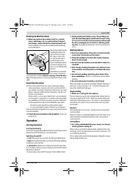
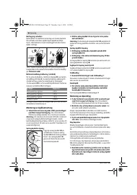
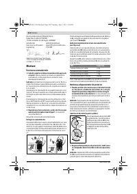
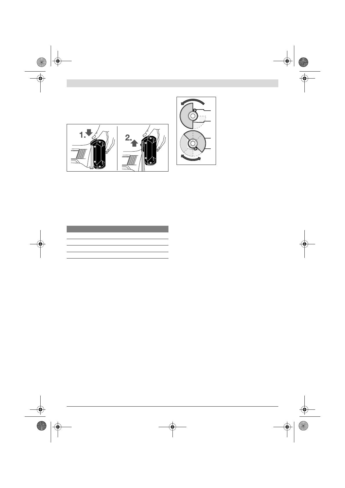
Removing the battery
The battery
5
is equipped with two locking levels that should
prevent the battery from falling out when pushing the battery
unlocking button
6
unintentionally. As long as the battery is
inserted in the power tool, it is held in position by means of a
spring.
To remove the battery
5
, press the unlocking button
6
and
pull out the battery toward the front.
Do not exert any force.
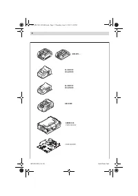
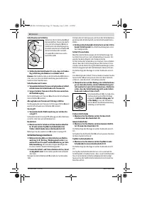
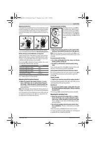
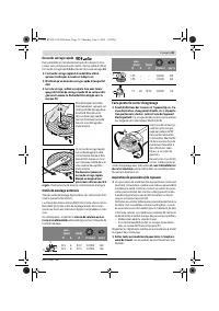
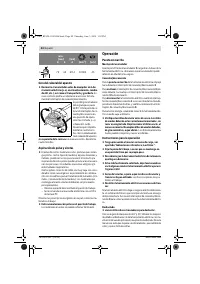
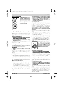
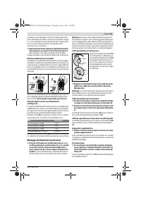
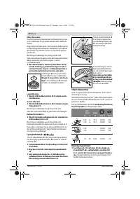
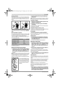
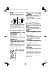
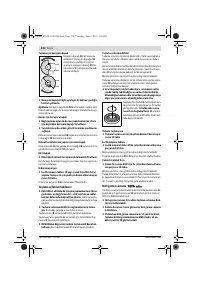
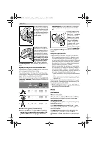
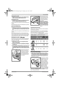
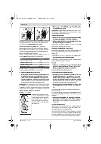
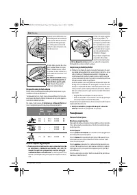
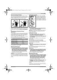
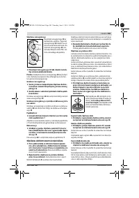
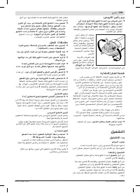
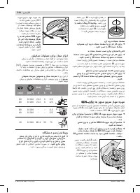
Battery Charge-control Indication (see figure A)
The three green LEDs of the battery charge-control indicator
24
indicate the charge condition of the battery
5
. For safety
reasons, it is only possible to check the status of the charge
condition when the machine is at a standstill.
Press button
23
to indicate the charge condition. This is also
possible when the battery
5
is removed.
When no LED lights up after pushing button
23
, then the bat-
tery is defective and must be replaced.
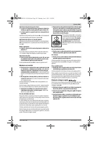
Mounting the Protective Devices
Before any work on the machine itself (e. g. mainte-
nance, tool change, etc.) as well as during transport
and storage, remove the battery from the power tool.
There is danger of injury when unintentionally actuating
the On/Off switch.
Note:
After breakage of the grinding disc during operation or
damage to the holding fixtures on the protection guard/power
tool, the machine must promptly be sent to an after-sales ser-
vice agent for maintenance. For addresses, see section “Af-
ter-sales Service and Application Service”.
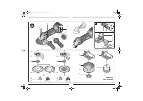
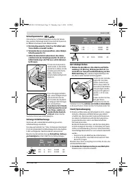
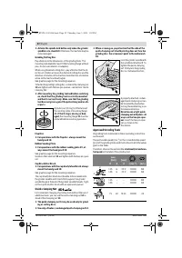
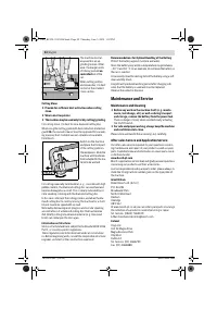
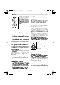
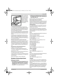
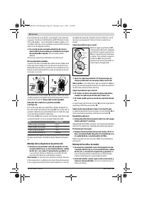
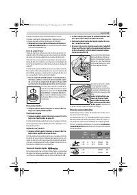
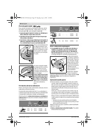
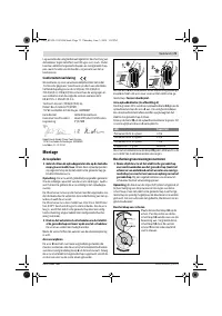
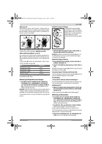
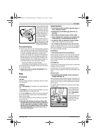
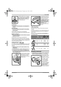
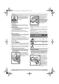
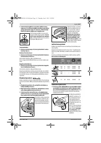
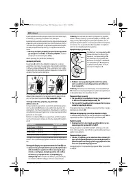
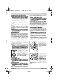
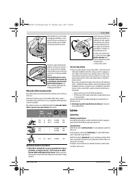
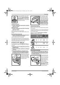
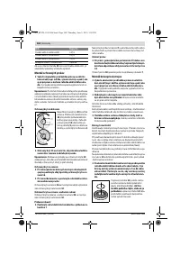
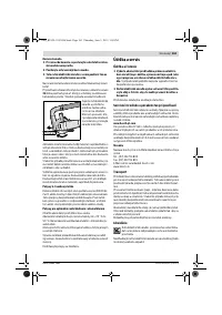
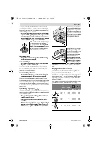
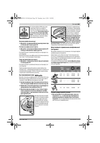
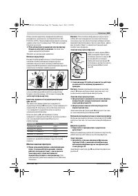
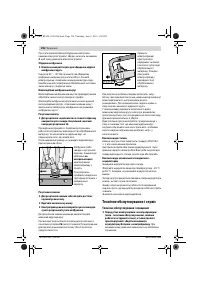
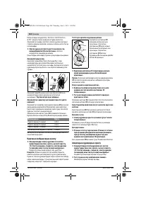
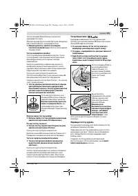
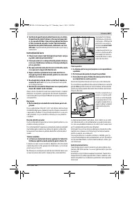
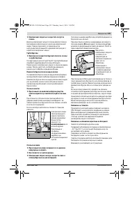
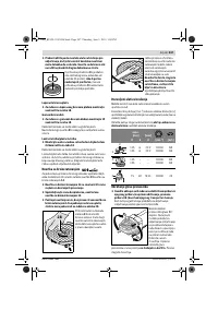
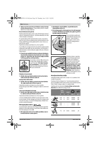
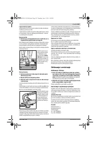
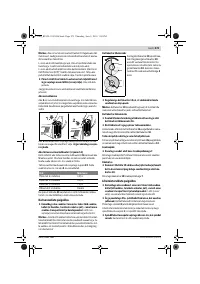
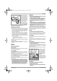
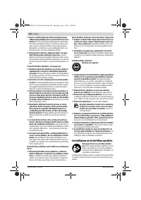
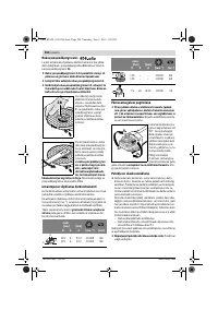
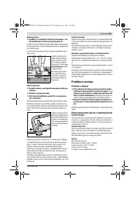
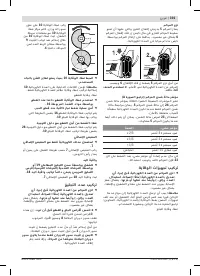
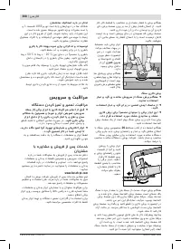
Protection Guard for Grinding
Place the protection guard
10
on
the spindle collar. Adjust the posi-
tion of the protection guard
10
to
the requirements of the operation.
Lock the protection guard
10
tight-
ening the locking screw
9
with a hex
key
4
.
Adjust the protection guard 10 in such a manner that
sparking is prevented in the direction of the operator.
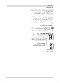
Note:
The encoding keys on the protection guard
10
ensure
that only a protection guard that fits the machine type can be
mounted.
Protection Guard for Cutting
For cutting with bonded abrasives, always use the pro-
tection guard for cutting 16.
Provide for sufficient dust extraction when cutting
stone.
The protection guard for cutting
16
is mounted in the same
manner as the protection guard for grinding
10
.
Cutting Guide with Dust Extraction Protection Guard
The cutting guide with dust extraction protection guard
26
is
mounted in the same manner as the protection guard for
grinding
10
.
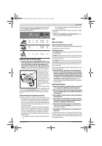
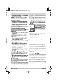
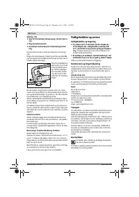
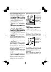
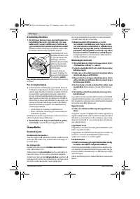
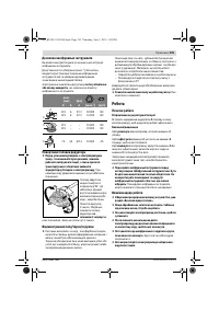
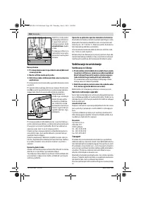
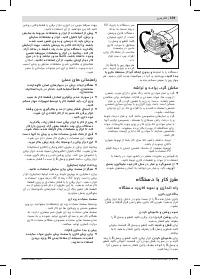
Auxiliary Handle
Operate your machine only with the auxiliary handle 7.
Screw the auxiliary handle
7
on the right or left of the machine
head depending on the working method.
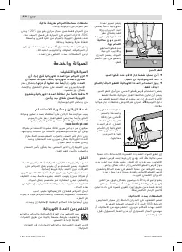
Hand Guard
For operations with the rubber sanding plate 19 or with
the cup brush/wheel brush/flap disc, always mount the
hand guard 18.
The hand guard
18
is fastened with the auxiliary handle
7
.
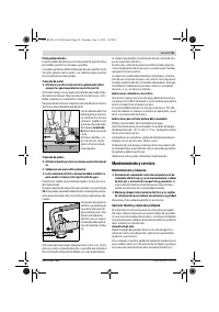
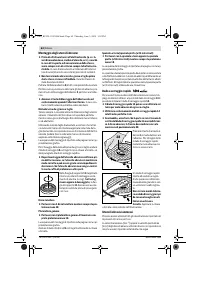
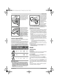
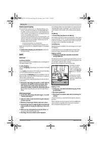
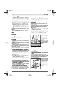
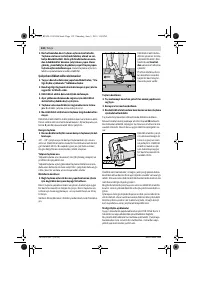
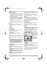
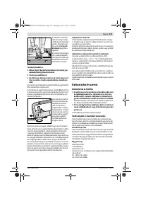
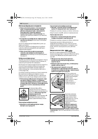
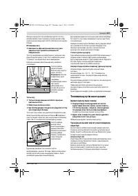
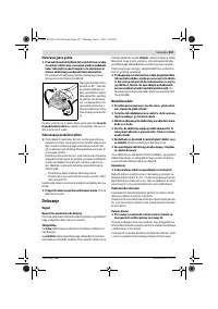
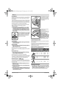
Mounting the Grinding Tools
Before any work on the machine itself (e. g. mainte-
nance, tool change, etc.) as well as during transport
and storage, remove the battery from the power tool.
There is danger of injury when unintentionally actuating
the On/Off switch.
Do not touch grinding and cutting discs before they
have cooled down.
The discs can become very hot while
working.
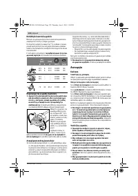
Clean the grinder spindle
8
and all parts to be mounted.
For clamping and loosening the grinding tools, lock the grind-
er spindle with the spindle lock button
2
.
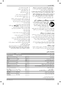
LED
Capacity
Continuous lighting 3 x green
≥
2/3
Continuous lighting 2 x green
≥
1/3
Continuous lighting 1 x green
< 1/3
Flashing light 1 x green
Reserve
OBJ_BUCH-1102-006.book Page 21 Thursday, June 5, 2014 1:02 PM
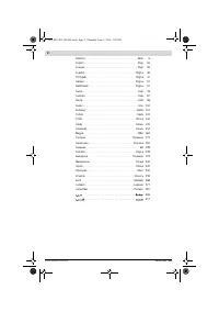
Содержание
- 175 Электробезопасность
- 176 Сервис
- 177 Не применяйте пильные цепи или пильные полотна.
- 178 Дополнительные предупредительные указания
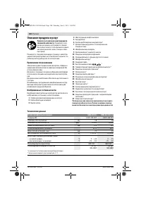
- 179 Описание продукта и услуг; Применение по назначению; Угловая шлифовальная машина
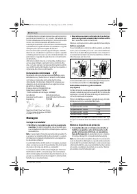
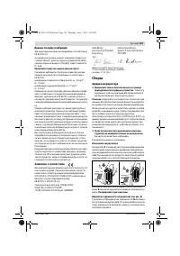
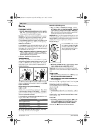
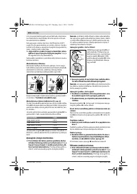
- 180 Данные по шуму и вибрации; Применяйте средства защиты органов слуха!; Заявление о соответствии; Сборка; Зарядка аккумулятора; Извлечение аккумулятора
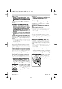
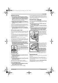
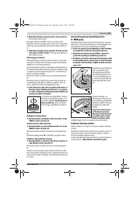
- 181 Установка защитных устройств; Защитный кожух для шлифования; Установка шлифовальных инструментов; Шлифовальный круг/oтрезной круг
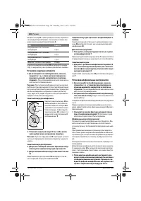
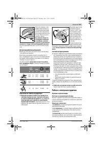
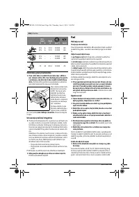
- 182 Веерный шлифовальный круг; Быстрозажимная гайка; число оборотов или до-; Поворот редукторной головки
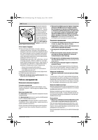
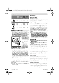
- 183 Отсос пыли и стружки; Работа с инструментом; Включение электроинструмента
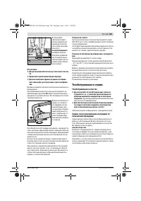
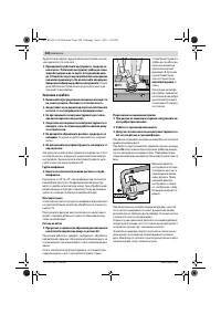
- 184 неконтролируемого; Техобслуживание и сервис; Техобслуживание и очистка
- 185 Россия; Транспортировка
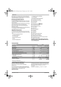
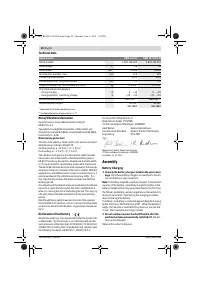
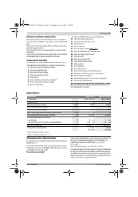
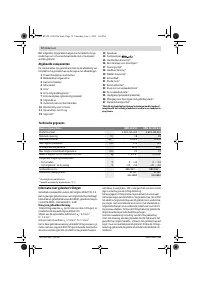
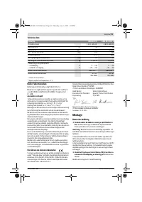
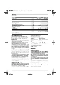
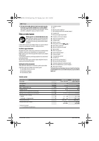
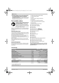
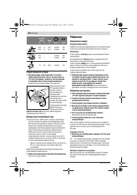
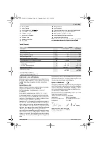
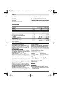
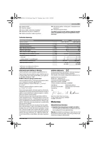
Характеристики

Остались вопросы?Не нашли свой ответ в руководстве или возникли другие проблемы? Задайте свой вопрос в форме ниже с подробным описанием вашей ситуации, чтобы другие люди и специалисты смогли дать на него ответ. Если вы знаете как решить проблему другого человека, пожалуйста, подскажите ему :)


