
Варочная панель FALMEC Quantum (600) - инструкция пользователя по применению, эксплуатации и установке на русском языке. Мы надеемся, она поможет вам решить возникшие у вас вопросы при эксплуатации техники.
Если остались вопросы, задайте их в комментариях после инструкции.
"Загружаем инструкцию", означает, что нужно подождать пока файл загрузится и можно будет его читать онлайн. Некоторые инструкции очень большие и время их появления зависит от вашей скорости интернета.


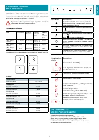


20
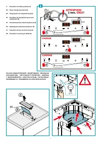
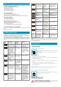
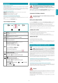
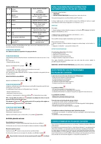
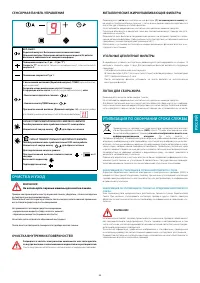
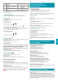
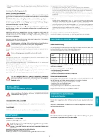
WHAT TO DO IN CASE OF COOKERS PROBLEMS
The cooker or cooking areas do not turn on:
· The cooker is not connected to the electric network.
· The protection fuse is released.
· Check if the block is not active.
· Keys are covered with water or grease.
· An object is placed on the keys.
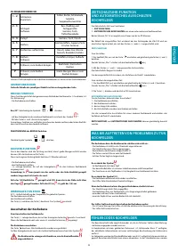
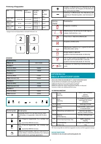
The symbol is displayed
.
· There is no saucepan on the cooking area.
· The container used is not compatible with cooktops.
· The diameter of the saucepan bottom is too small compared to the cooking area.
The symbol [E] is displayed:
· Disconnect and connect the cooker.
· Contact the after-sales centre.
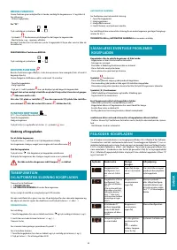
One of the area or the entire cooker turns o
ff
:
· The safety overheating system is active;
· The cooker or one cooking area remains on for too long;
· one or more keys are covered;
· one of the saucepans is empty and the bottom overheated.
The fan keeps on working after the cooker shutdown:
· This is not a malfunction: the fan keeps on protecting the electronic power unit of the
device.
· The fan stops automatically.
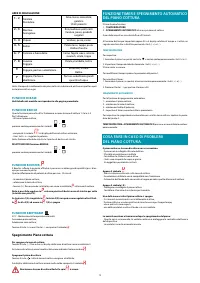
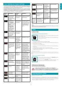
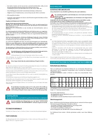
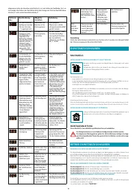
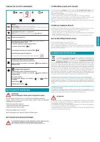
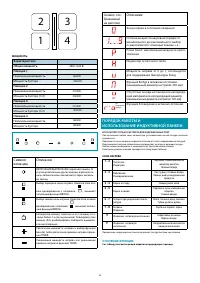
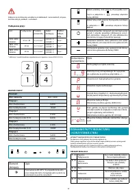
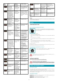
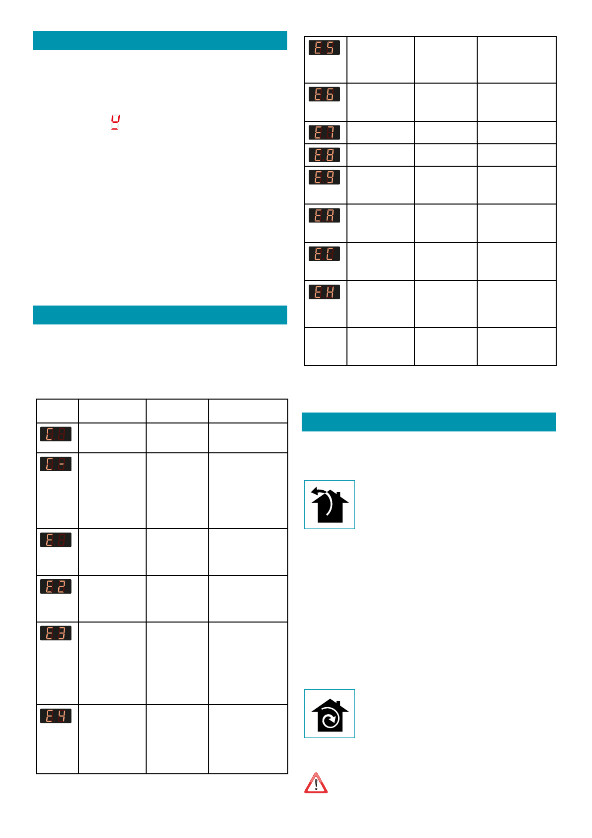
COOKERS ERROR CODES
For supporting a service technician in case of error, the UI displays error codes.
In combination with the provided document "error codes Basic 2" which includes datai-
led information a complete error matrix description is available.
E.G.O's standard error codes are listed following, customized UI can be di
ff
erent. In the
standard general UI eroors (Er xx) and cooking zone errors (E/x) di
ff
er. In case of cooking
zone errors the display of the incorrect cooking zone blinks alternative "E" and a hexco-
de "X".
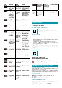
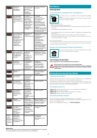
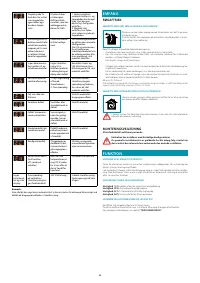
Error
code
Description
possible
causes
Remedy
.
The cooking zone
can be con
fi
gured if
a static "C" is shown
No error, the user
is in the service
menu.
A suitably pan must be
placed on the relevant
cooking zone
.
The cooking will be
con
fi
gured if a
fl
a-
shing "C" is shown.
After a successful
con
fi
guration the
relevant display
shows "-". If "-" is not
displayed check the
possible causes of
the E/5
User is in the
service menu, no
error
Wait for the symbol "-"
or abort the con
fi
gu-
ration activities by
pressing the select key
and the "C" will not
fl
ash
anymore.
.
A
fl
ashing "E" on
each cooking zone
indicates that all
con
fi
gs will be
deleted
User is in service
menu, no error
Manual con
fi
guration
.
Temperature limits
are exceeded
Pt or glass tempe-
rature is too high
NTC -> electronic
temperature too
high
System must cool down
.
Unsuitable pot, e.g.
loss of the magnetic
characteristics be-
cause of temperatu-
re in the bottom
On the module
a pot creates
an improper
operatioing point
which can destroy
devices, e.g IGBTs.
1. The error is automa-
tically cancelled after 8
s and the cooking zone
can be used again. In
case of further upco-
ming errors the pot has
to be replaced.
2. The module has to
be changed if the error
comes without a pot on
the cooking zone.
.
Uncon
fi
gured in-
duction module (all
induction module
answer to UI, but
any element is rela-
ted to the e
ff
ected
cooking zone.)
induction module
is not con
fi
gured
Delete the hob con
fi
gu-
ration and activate the
manual con
fi
guration.
Start the UI service
menu to con
fi
gure the
induction module if the
listed points are not
successful replace the
module.
.
No communication
between UI and
induction module
No power supply
of induction
module.
Bad cabling or
defect
Check power and LIN
connections. If con-
nection is OK, replace
the module
.
Main power distur-
bance
1. Failure in main
power frequency
detection
2. Overvoltage
Check main power
voltage and frequency,
if ok replace the module
.
Non assignable
failure
Replace module or User
interface
.
Fan failure
Fan or control
electronic is defect
Replace the module
.
Defect ive tempe-
rature probe on
inductor
Sensor signal out
of valid range; sen-
sor or electronic is
defect
Replace the module
.
Hardware defect of
induction module
Defect hardware
device detected
by the self-check
of the module
Replace the module
.
Con
fi
guration failure 2 cooking zones
are delicated to
the same element
of the UI
Delete the actual con
fi
-
guration
manual con
fi
guration
with service menu
.
Fixed sensor value
(test function for T
probe on inductor)
Not enough tem-
perature change
(10 K) within 5 min
after switch on
the hob
System must cool down
No
functiona-
lity and no
displaying
Overvoltage on
the switch mode
power supply (no
functionality)
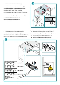
400 V connection
Disconnect and correct
the power line con-
nection
Note:
Not each failure can be delected automatically by the system, e.g. in case of defect of the
User interface power supply.
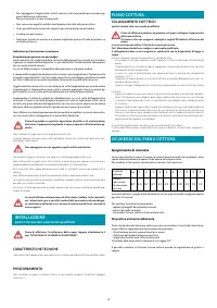
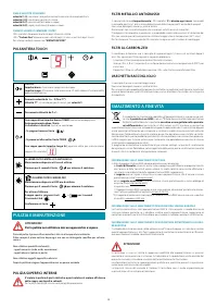
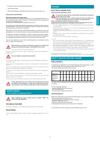
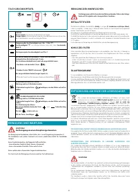
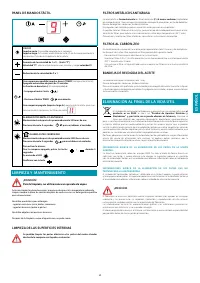
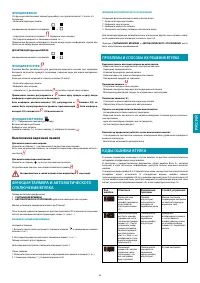
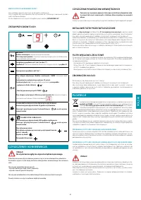
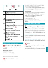
COOKER HOOD
FUMES DISCHARGE
EXTERNAL EXHAUST HOOD
(
SUCTION
)
In this version the fumes and vapours are discharged outside through
the exhaust pipe.
To this end, the hood outlet
fi
tting must be connected via a pipe, to an
external output.
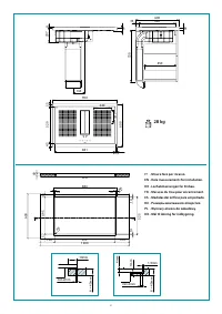
The outlet pipe must have:
• a diameter not less than that of the hood
fi
tting.
• a slight slope downwards (drop) in the horizontal sections to prevent condensation from
fl
owing back into the motor.
• the minimum required number of bends.
• the minimum required length to avoid vibrations and reduce the suction performance of
the hood.
You are required to insulate the pipes if it passes through cold environments.
In the presence of motors with 800m
3
/h or higher, a check valve is present to prevent
external air
fl
owing back.
Deviation for Germany:
when the kitchen hood is used at the same time as appliances that are powered by energy other
than electricity, the negative pressure in the room must not exceed 4 Pa (4 x 10⁻⁵ bar).
HOOD WITH INTERNAL RECIRCULATION
(
FILTERING
)
In this model, the air passes through the charcoal
fi
lters (optionale) to
be puri
fi
ed and recycled in the environment.
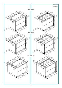
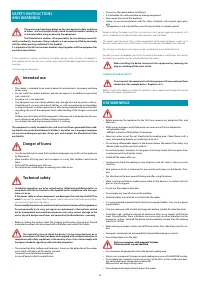
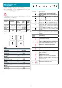
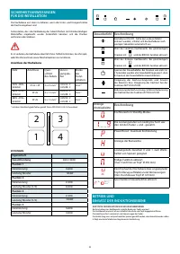
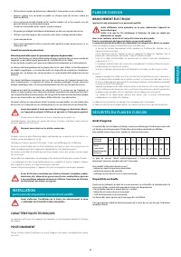
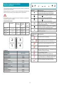
ASSEMBLY INSTRUCTIONS
only intended for quali
fi
ed personnel
The hood can be installed in various con
fi
gurations.
The generic assembly steps apply to all installations; for each case, follow
the speci
fi
c steps provided for the required installation.
Характеристики

Остались вопросы?Не нашли свой ответ в руководстве или возникли другие проблемы? Задайте свой вопрос в форме ниже с подробным описанием вашей ситуации, чтобы другие люди и специалисты смогли дать на него ответ. Если вы знаете как решить проблему другого человека, пожалуйста, подскажите ему :)


