
Материнские платы ASRock B660M Pro RS - инструкция пользователя по применению, эксплуатации и установке на русском языке. Мы надеемся, она поможет вам решить возникшие у вас вопросы при эксплуатации техники.
Если остались вопросы, задайте их в комментариях после инструкции.
"Загружаем инструкцию", означает, что нужно подождать пока файл загрузится и можно будет его читать онлайн. Некоторые инструкции очень большие и время их появления зависит от вашей скорости интернета.


English
18
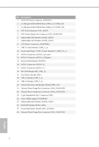
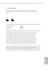
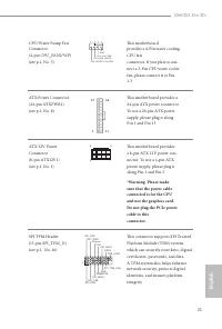
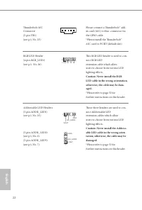
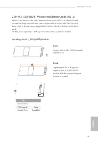
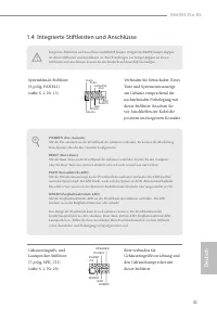
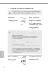
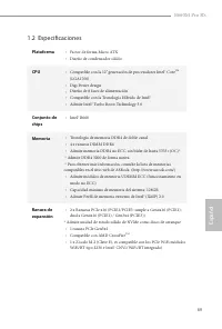
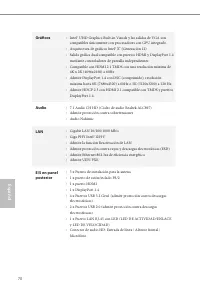
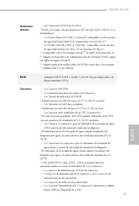
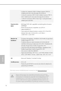
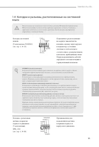
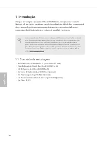
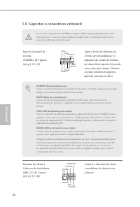
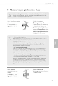
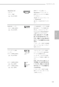
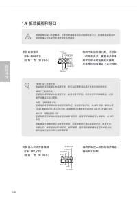
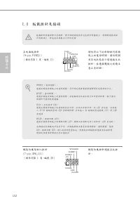
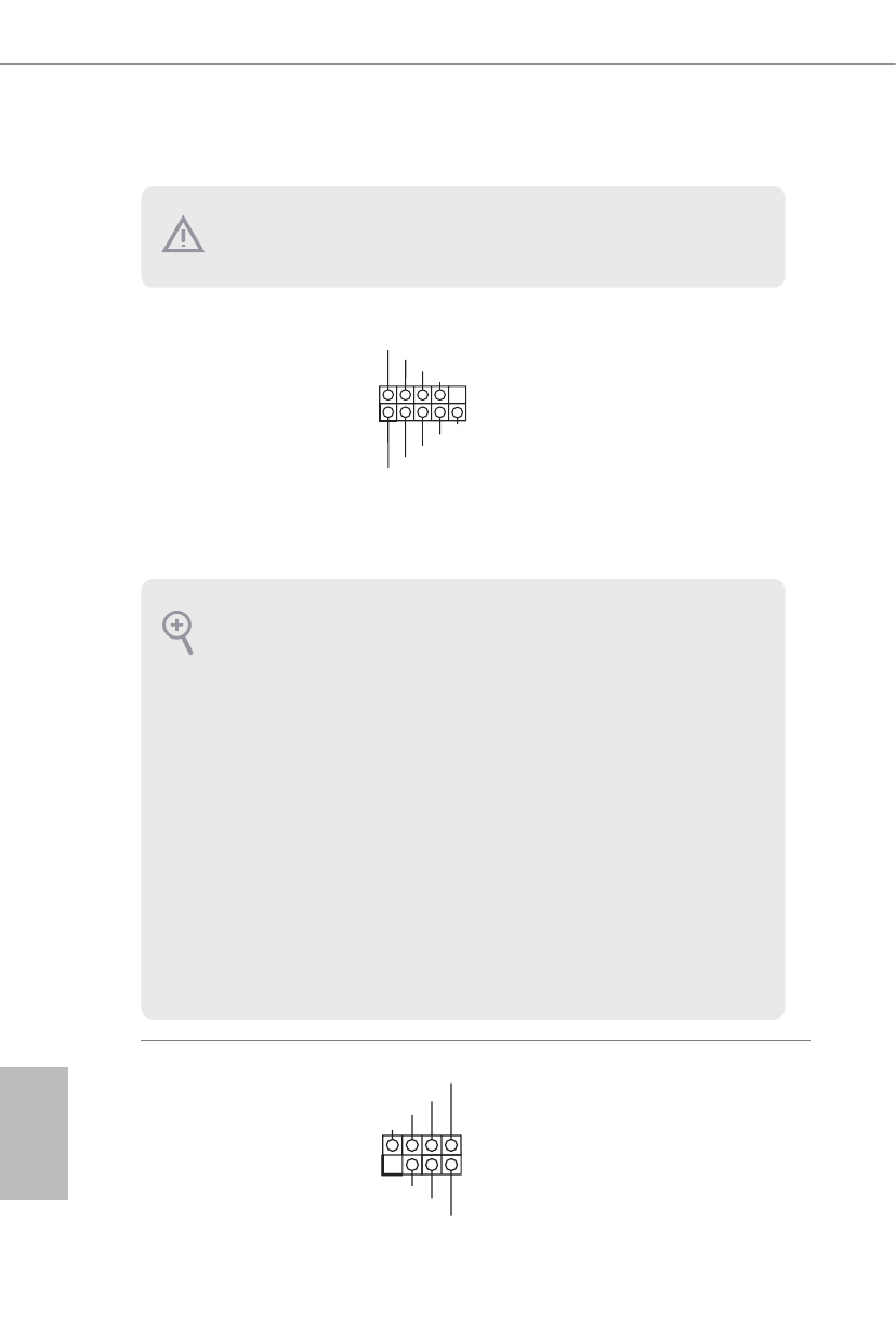
2.6 Onboard Headers and Connectors
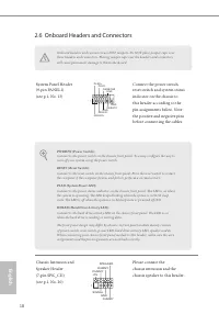
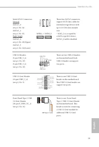
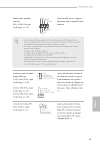
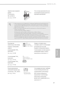
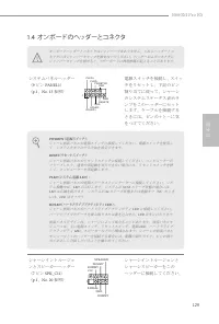
System Panel Header
(9-pin PANEL1)
(see p.1, No. 13)
Connect the power switch,
reset switch and system status
indicator on the chassis to
this header according to the
pin assignments below. Note
the positive and negative pins
before connecting the cables.
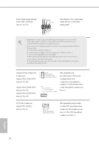
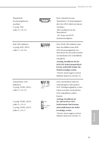
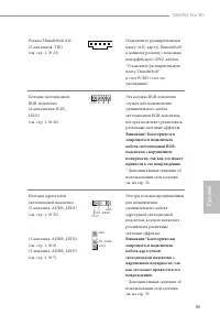
Chassis Intrusion and
Speaker Header
(7-pin SPK_CI1)
(see p.1, No. 20)
Please connect the
chassis intrusion and the
chassis speaker to this header.
PWRBTN (Power Switch):
Connect to the power switch on the chassis front panel. You may configure the way to
turn off your system using the power switch.
RESET (Reset Switch):
Connect to the reset switch on the chassis front panel. Press the reset switch to restart
the computer if the computer freezes and fails to perform a normal restart.
PLED (System Power LED):
Connect to the power status indicator on the chassis front panel. The LED is on when
the system is operating. The LED keeps blinking when the system is in S1/S3 sleep
state. The LED is off when the system is in S4 sleep state or powered off (S5).
HDLED (Hard Drive Activity LED):
Connect to the hard drive activity LED on the chassis front panel. The LED is on
when the hard drive is reading or writing data.
The front panel design may differ by chassis. A front panel module mainly consists
of power switch, reset switch, power LED, hard drive activity LED, speaker and etc.
When connecting your chassis front panel module to this header, make sure the wire
assignments and the pin assignments are matched correctly.
Onboard headers and connectors are NOT jumpers. Do NOT place jumper caps over
these headers and connectors. Placing jumper caps over the headers and connectors
will cause permanent damage to the motherboard.
G N D
R E S E T #
P W R B T N #
P L E D -
P L E D +
G N D
H D L E D -
H D L E D +
1
G N D
1
+5V
DUMMY
SIGNAL
GND
DUMMY
SPEAKER
DUMMY
Характеристики

Остались вопросы?Не нашли свой ответ в руководстве или возникли другие проблемы? Задайте свой вопрос в форме ниже с подробным описанием вашей ситуации, чтобы другие люди и специалисты смогли дать на него ответ. Если вы знаете как решить проблему другого человека, пожалуйста, подскажите ему :)
