
Компрессоры Stanley D 211/8/24 100546056 - инструкция пользователя по применению, эксплуатации и установке на русском языке. Мы надеемся, она поможет вам решить возникшие у вас вопросы при эксплуатации техники.
Если остались вопросы, задайте их в комментариях после инструкции.
"Загружаем инструкцию", означает, что нужно подождать пока файл загрузится и можно будет его читать онлайн. Некоторые инструкции очень большие и время их появления зависит от вашей скорости интернета.


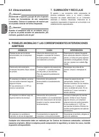


22
G
B
●
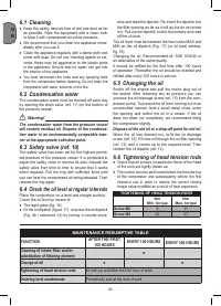
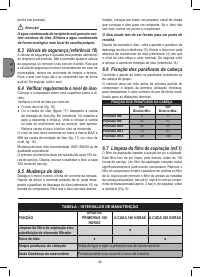
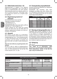
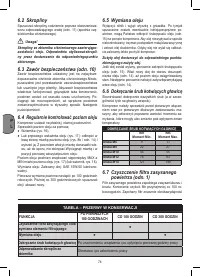
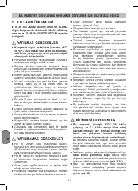
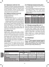
Single-phase versions are fitted with a pressure
switch equipped with a delayed closing air discharge
valve which facilitates start-up of the motor.
Therefore venting of air from this valve for a few
seconds with the receiver empty is normal.
●
All the compressors are fitted with a safety valve
that is tripped in the case of malfunctioning of the
pressure switch in order to assure machine safety.
The safety valve is set to avoid over-pressurization
of the air tanks. This valve is factory pre-set and
will not function unless tank pressure reaches this
pressure. Do not attempt to adjust or eliminate this
safety device.
Any adjustments to this valve could cause serious
injury. If this device requires service or maintenance,
see an Authorized Service Center.
●
The red notch on the pressure gauge refers to the
maximum operating pressure of the tank. It does not
refer to the adjusted pressure.
●
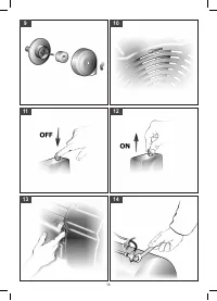
When fitting a tool, the flow of air in output must be
switched off.
●
When using compressed air, you must know and
comply with the safety precautions to be adopted for
each type of application (inflation, pneumatic tools,
painting, washing with water-based detergents only,
etc.)
.
●
Please check that the air consumption and the
maximum working pressure of the pneumatic tool
and connection pipes (with the compressor) to
be used, are compatible with the pressure set on
the pressure regulator and with the amount of air
supplied by the compressor.
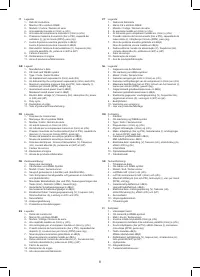
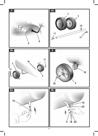
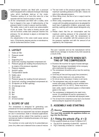
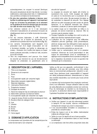
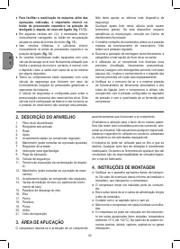
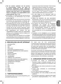
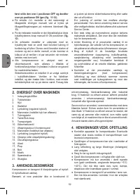
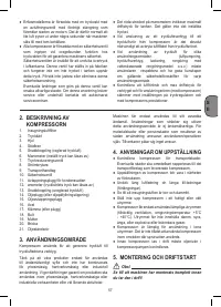
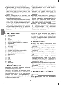
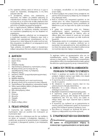
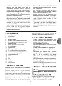
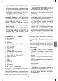
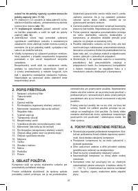
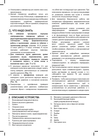
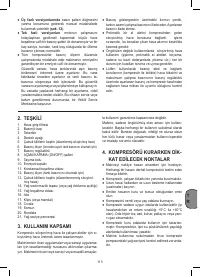
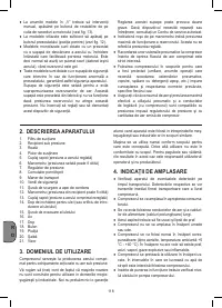
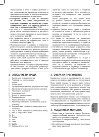
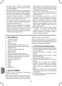
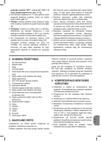
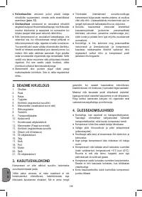
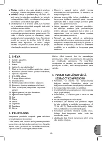
2. LAYOUT
1. Intake air filter
2. Pressure vessel
3. Wheel
4. Supporting foot
5. Quick-lock coupling (regulated compressed air)
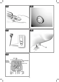
6. Pressure gauge (for reading the preset pressure
by means of the pressure regulator)
7. Pressure regulator
8. ON/OFF switch
9. Transportation handle
10. Safety valve
11. Drain valve
12. Pressure gauge (for reading the tank pressure)
13. Quick-lock coupling (unregulated compressed air)
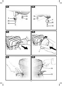
14. Oil dipstick (or oil filler opening)
15. Oil drainage screw
16. Axle
17. Clip
18. Bolt
19. Nut
20. Washer
21. Oil level window
3. SCOPE OF USE
The compressor is designed for generating com
-
pressed air for tools operated by compressed air.
Please note that our equipment has not been designed
for use in commercial, trade or industrial applications.
Our warranty will be voided if the machine is used in
commercial, trade or industrial businesses or for equiv-
alent purposes.
The machine is to be used only for its prescribed pur
-
pose. Any other use is deemed to be a case of misuse.
The user / operator and not the manufacturer will be
liable for any damage or injuries of any kind caused as
a result of this.
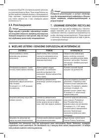
4. POINTS TO NOTE WHEN SET-
TING UP THE COMPRESSOR
●
Examine the machine for signs of transit damage.
Report any damage immediately to the company
which delivered the compressor.
●
The compressor should be set up near the working
consumer.
●
Avoid long air lines and long supply lines (extensions).
●
Make sure the intake air is dry and dust-free.
●
Do not set up the compressor in damp or wet rooms.
●
The compressor may only be used in suitable
rooms (with good ventilation and an ambient tem-
perature from +5°C to +40°C). There must be no
dust, acids, vapors, explosive gases or inflammable
gases in the room.
●
The compressor is designed to be used in dry
rooms. It is prohibited to use the compressor in
areas where work is conducted with sprayed water.
●
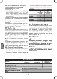
The oil level in the compressor pump has to be checked
before putting the equipment into operation.
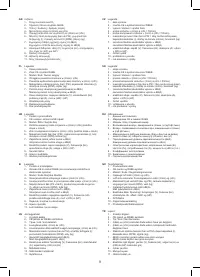
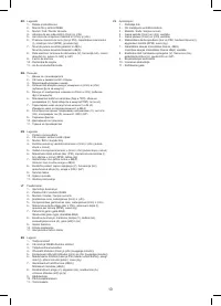
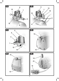
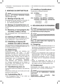
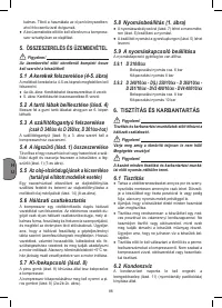
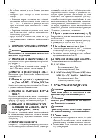
5. ASSEMBLY AND STARTING
Warning!
You must fully assemble the appliance before us-
ing it for the first time.
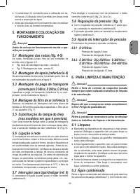
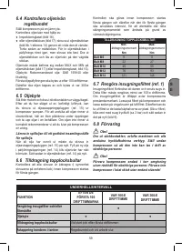
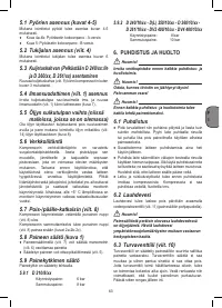
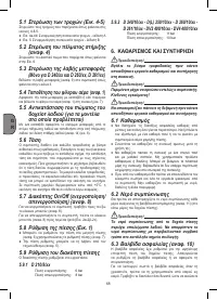
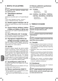
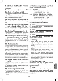
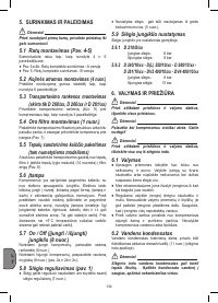
5.1 Fitting the wheels (Fig. 4 ÷ 5)
Fit the supplied wheels as shown in figures 4 & 5:
●
Fig.4a & 4b: Assembly of wheel kit - version A
●
Fig.5: Assembly of wheel kit - version B


