
Фрезеры Bosch 0.601.624.020 - инструкция пользователя по применению, эксплуатации и установке на русском языке. Мы надеемся, она поможет вам решить возникшие у вас вопросы при эксплуатации техники.
Если остались вопросы, задайте их в комментариях после инструкции.
"Загружаем инструкцию", означает, что нужно подождать пока файл загрузится и можно будет его читать онлайн. Некоторые инструкции очень большие и время их появления зависит от вашей скорости интернета.


24
| English
1 609 92A 0B3 | (30.4.14)
Bosch Power Tools
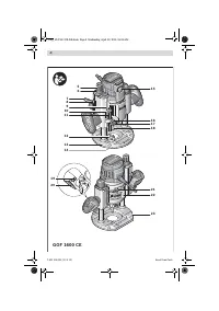
with the clamping lever
25
released, is locked in one of the
3 notches
26
. The notches each have a clearance of
12.7 mm (0.5 ").
– The adjustment knob for depth-of-cut fine adjustment
24
is used for fine adjustment of the routing depth; turn clock-
wise to increase the routing depth, and anticlockwise to
decrease the routing depth. The travel on the scale of ad-
justment knob
24
is indicated in inch and millimeter. The
maximum setting range is 41 mm. The scale for depth-of-
cut adjustment
34
provides added orientation.
Example:
The desired depth-of-cut is to be 10.0 mm; the
trial cut resulted in a cutting depth of 9.5 mm.
– Set the scale of the adjustment knob
24
to “0” without
changing the setting of the adjustment knob
24
itself. Then
set the adjustment knob
24
to the value “0.5” by turning in
clockwise direction.
– Check the selected depth-of-cut by carrying out another
trial cut.
Working Advice
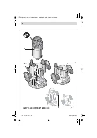
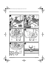
Direction of Feed and Routing Process (see figure I)
The routing process must always be carried out against
the rotation direction of the router bit 18 (up-cutting
motion). When routing in the direction with the rota-
tion of the router (down-cutting), the machine can
break loose, eliminating control by the user.
For routing with the plunge base
2
, proceed as follows:
– Adjust the required depth-of-cut; see Section “Adjusting
the Depth-of-cut”.
– Place the machine with the router bit mounted on the
workpiece to be machined and switch the power tool on.
– Press the release lever for plunge action
7
down and slowly
guide the router down until the set depth-of-cut is reached.
Let go of release lever
7
again to lock this plunging depth.
– Carry out the routing process applying uniform feed.
– After finishing the routing process, guide the router up to
the uppermost position.
– Switch the power tool off.
For routing with the non-plunge base
3
, proceed as follows:
–
Note:
Take into consideration that for routing work with
the non-plunge base
3
, the router bit
18
always protrudes
out of the base plate
13
. Do not damage the template or
the workpiece.
– Adjust the required depth-of-cut; see Section “Adjusting
the Depth-of-cut”.
– Switch the machine on and guide it to the location subject
to routing.
– Carry out the routing process applying uniform feed.
– Switch the power tool off. Do not place the power tool
down until the router bit has come to a standstill.
Routing with Auxiliary Guide (see figure J)
For working large workpieces, e. g., when routing grooves, a
board or straight edge can be securely fastened to the work-
piece as an auxiliary guide. The multifunction router can be
guided alongside the path of this auxiliary guide. When using
the plunge base
2
, guide the guide plate (flattened side) of the
multifunction router alongside the auxiliary guide.
Shaping or Molding Applications
For shaping or molding applications without the use of a par-
allel guide, the router bit must be equipped with a pilot or a
ball bearing.
– Guide the switched on power tool from the side toward the
workpiece until the pilot or the ball bearing of the router bit
faces against the workpiece edge to be machined.
– Guide the power tool alongside the workpiece edge with
both hands, paying attention that the router is positioned
rectangular. Too much pressure can damage the edge of
the workpiece.
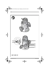
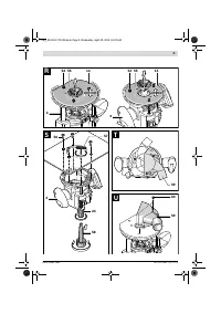
Routing with Parallel Guide (see figure K)
Slide the parallel guide
35
with the guide rods
36
into the
base plate
13
and tighten as required with the wing bolts
41
.
Additionally, the parallel guide can be adjusted lengthwise
with the wing bolts
37
and
38
.
Fine adjustment of the length is possible with the fine-adjust-
ment knob
39
after loosening both wing bolts
37
. One revolu-
tion corresponds with a setting range of 2.0 mm. One gradu-
ation mark on the fine-adjustment knob
39
changes the
setting range by 0.1 mm.
The effective contact surface of the parallel guide can be ad-
justed with the edge guide
40
.
Guide the switched on power tool with uniform feed and later-
al pressure on the parallel guide alongside the workpiece
edge.
Routing with the Router Compass (see figure L)
The router compass/guide-rail adapter
42
can be used for cir-
cular routing jobs. Mount the router compass as shown in the
figure.
Screw the centring screw
47
into the thread on the router
compass. Insert the point of the centring screw into the cen-
tre of the circular arc to be routed, paying attention that point
of the screw engages into the workpiece surface.
Coarsely adjust the required radius by moving the router com-
pass and tighten the wing bolts
44
and
45
.
The length can be fine adjusted with the fine-adjustment knob
46
after loosening the wing bolt
45
. One revolution corre-
sponds with a setting range of 2.0 mm. One graduation mark
on the fine-adjustment knob
46
changes the setting range by
0.1 mm.
Guide the switched on power tool over the workpiece with the
right handle
4
and the router compass handle
43
.
Routing with Guide Rail (see figure M)
Straight routing cuts can be carried out with help of the guide
rail
49
.
The base spacer
48
must be mounted in order to compensate
the height difference.
Mount the router compass/guide-rail adapter
42
as shown in
the figure.
Fasten the guide rail
49
to the workpiece with suitable clamp-
ing devices, e. g. screw clamps. Place the machine with the
guide-rail adapter
42
mounted onto the guide rail.
OBJ_BUCH-1178-004.book Page 24 Wednesday, April 30, 2014 10:24 AM
Содержание
- 151 Указания по безопасности
- 153 Описание продукта и услуг; Применение по назначению
- 154 Технические данные; Заявление о соответствии
- 155 Сборка; Отсос пыли и стружки
- 156 Работа с инструментом; Включение электроинструмента
- 157 Указания по применению
- 159 Техобслуживание и сервис; Техобслуживание и очистка
- 160 Утилизация
Характеристики

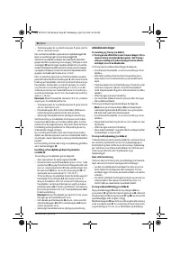
Остались вопросы?Не нашли свой ответ в руководстве или возникли другие проблемы? Задайте свой вопрос в форме ниже с подробным описанием вашей ситуации, чтобы другие люди и специалисты смогли дать на него ответ. Если вы знаете как решить проблему другого человека, пожалуйста, подскажите ему :)


