Шлифмашины Bosch 18V-10 solo (0.601.9J4.002) - инструкция пользователя по применению, эксплуатации и установке на русском языке. Мы надеемся, она поможет вам решить возникшие у вас вопросы при эксплуатации техники.
Если остались вопросы, задайте их в комментариях после инструкции.
"Загружаем инструкцию", означает, что нужно подождать пока файл загрузится и можно будет его читать онлайн. Некоторые инструкции очень большие и время их появления зависит от вашей скорости интернета.

English |
33
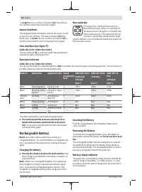
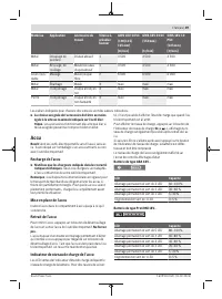
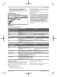
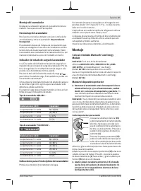
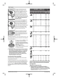
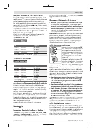
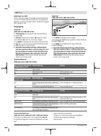
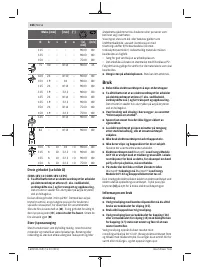
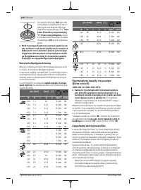
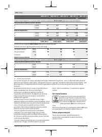
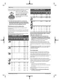
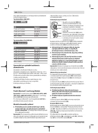
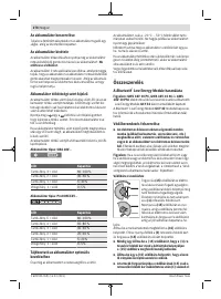
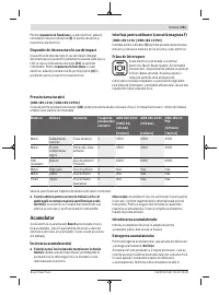
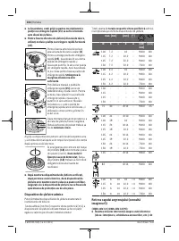
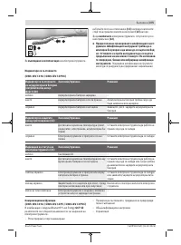
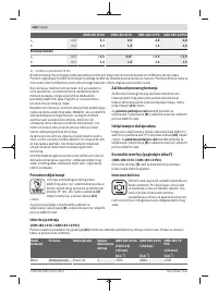
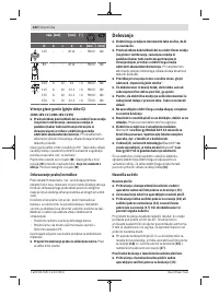
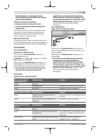
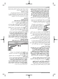
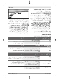
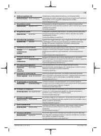
Press the button for the battery charge indicator or
to
show the state of charge. This is also possible when the bat-
tery is removed.
If no LED lights up after pressing the button for the battery
charge indicator, then the battery is defective and must be
replaced.
The state of charge of the battery is also displayed on the
user interface Status indications.
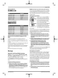
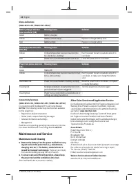
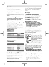
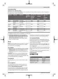
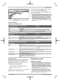
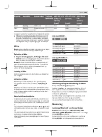
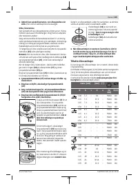
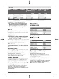
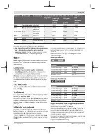
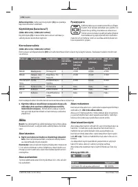
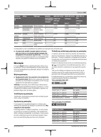
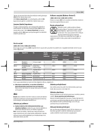
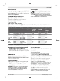
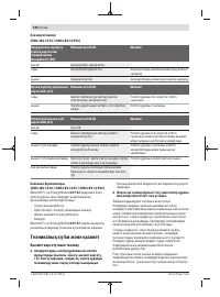
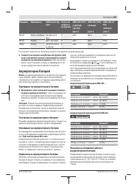
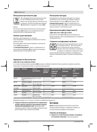
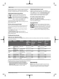
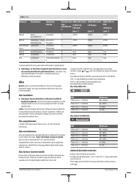
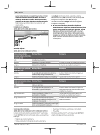
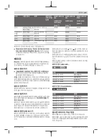
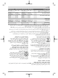
Battery model GBA 18V...
LED
Capacity
3× continuous green light
60–100 %
2× continuous green light
30–60 %
1× continuous green light
5–30 %
1× flashing green light
0–5 %
Battery model ProCORE18V...
LED
Capacity
5 × continuous green light
80–100 %
4 × continuous green light
60–80 %
3 × continuous green light
40–60 %
2 × continuous green light
20–40 %
1 × continuous green light
5–20 %
1 × flashing green light
0–5 %
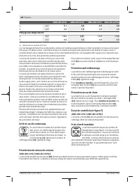
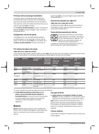
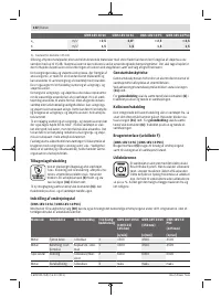
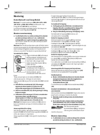
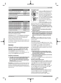
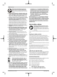
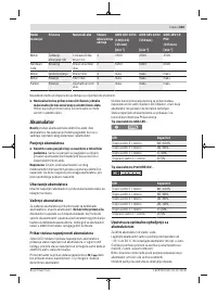
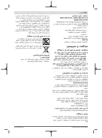
Recommendations for Optimal Handling of the
Battery
Protect the battery against moisture and water.
Only store the battery within a temperature range of −20 to
50 °C. Do not leave the battery in your car in the summer, for
example.
Occasionally clean the ventilation slots on the battery using a
soft brush that is clean and dry.
A significantly reduced operating time after charging indic-
ates that the battery has deteriorated and must be replaced.
Follow the instructions on correct disposal.
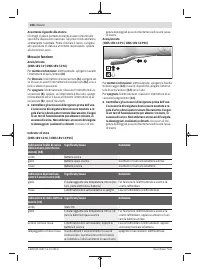
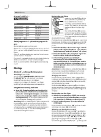
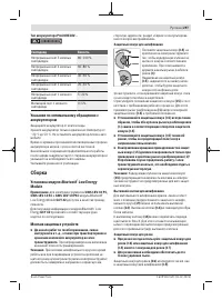
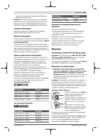
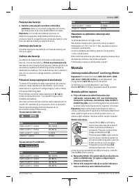
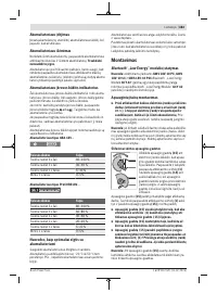
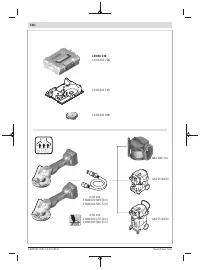
Fitting
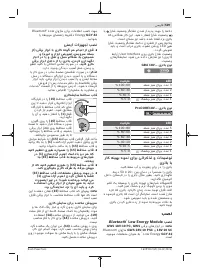
Using the
Bluetooth
®
Low Energy Module
Note:
The
Bluetooth
®
Low Energy Module
GCY 42
is avail-
able as an accessory with
GWS 18V-10 PC, GWS 18V-10
SC
and
GWS 18V-10 PSC
power tools.
Read the corresponding operating instructions for informa-
tion about the
Bluetooth
®
Low Energy Module
GCY 42
.
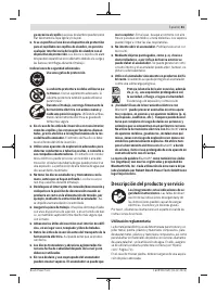
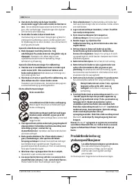
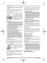
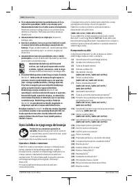
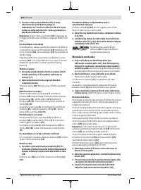
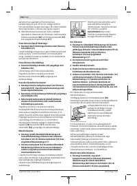
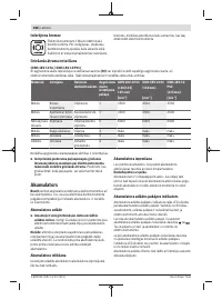
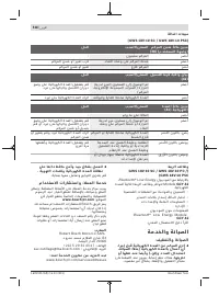
Fitting Protective Equipment
u
Remove the battery from the power tool before carry-
ing out work on the power tool (e.g. maintenance,
changing tool, etc.). The battery should also be re-
moved for transport and storage.
There is risk of injury
from unintentionally pressing the on/off switch.
Note:
If the grinding disc breaks during operation or the
holding fixtures on the protective guard/power tool become
damaged, the power tool must be sent to the after-sales ser-
vice immediately; see the "After-Sales Service and Applica-
tion Service" section for addresses.
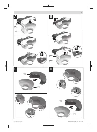
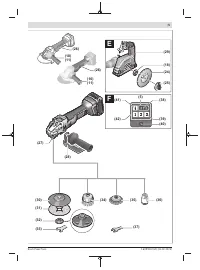
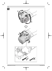
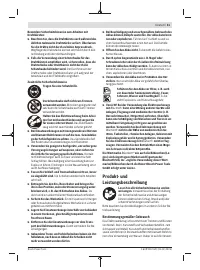
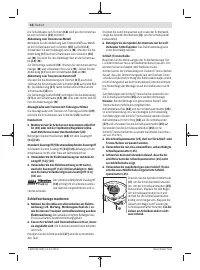
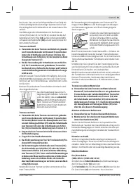
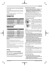
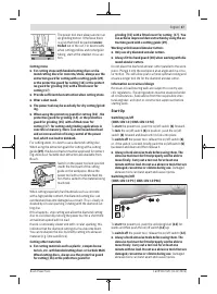
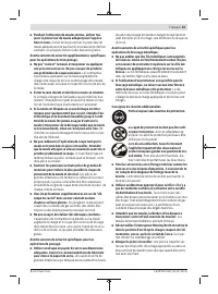
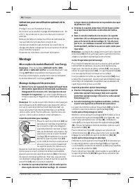
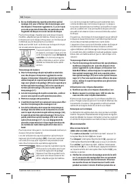
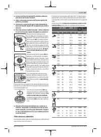
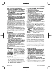
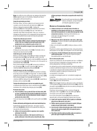
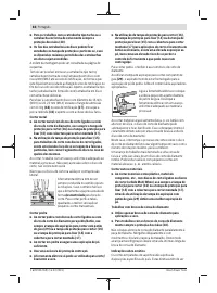
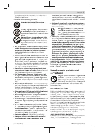
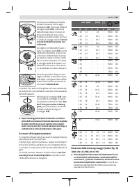
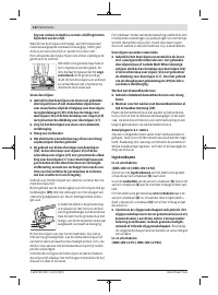
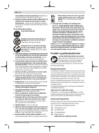
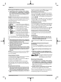
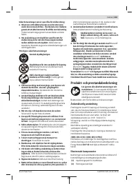
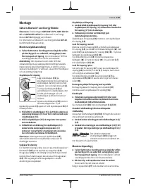
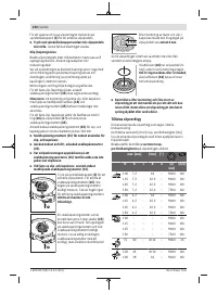
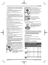
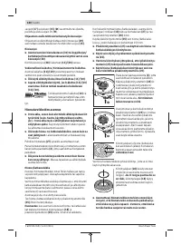
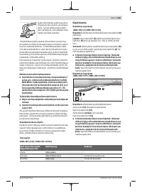
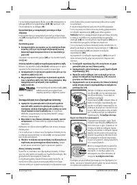
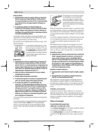
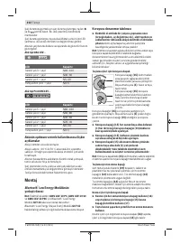
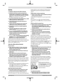
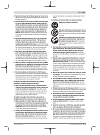
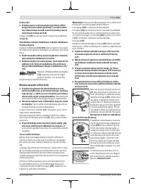
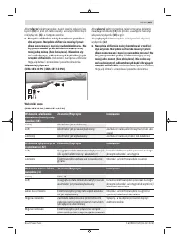
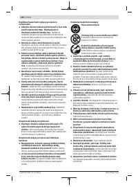
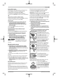
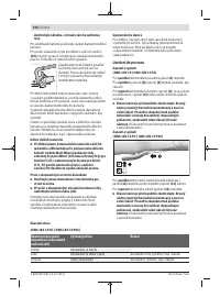
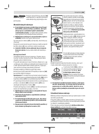
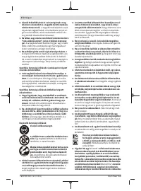
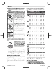
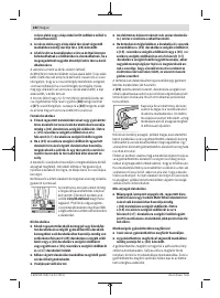
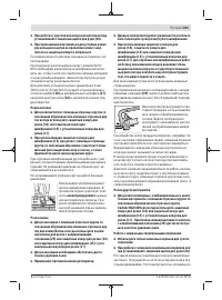
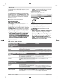
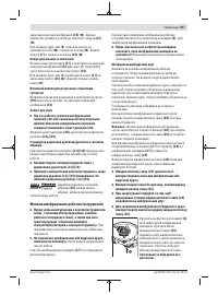
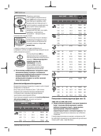
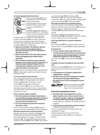
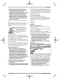
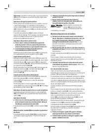
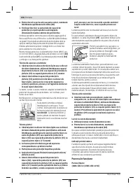
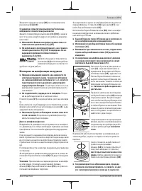
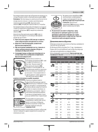
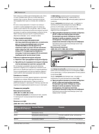
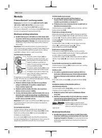
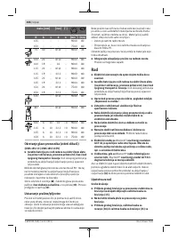
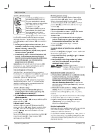
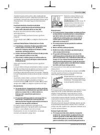
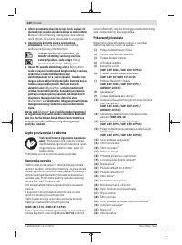
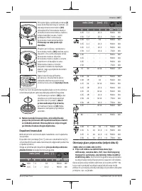
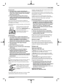
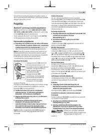
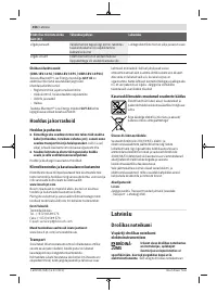
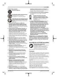
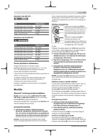
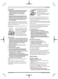
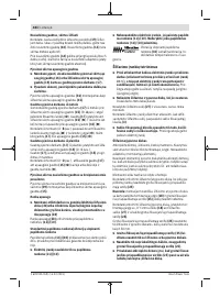
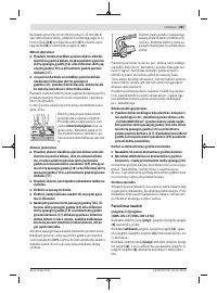
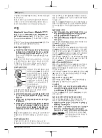
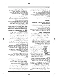
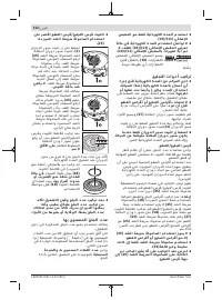
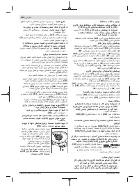
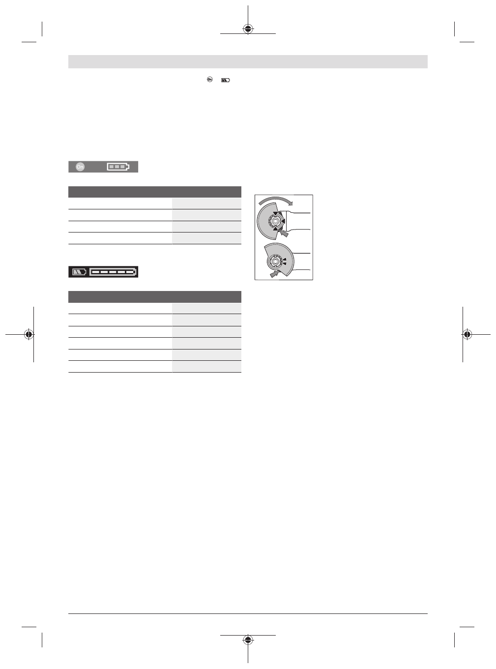
Protective guard for grinding
Place the protective guard
(15)
onto
the holder on the power tool until the
coding cams of the protective guard
are aligned with the holder. When do-
ing so, press and hold the unlocking
lever
(1)
.
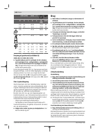
Press the protective guard
(15)
onto
the spindle collar until the shoulder of
the protective guard is sitting on the
flange of the power tool and rotate the
protective guard until it audibly clicks
into place.
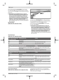
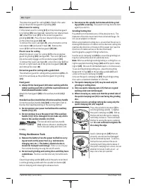
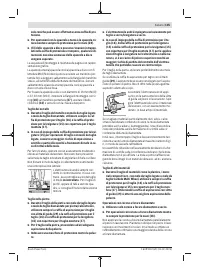
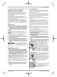
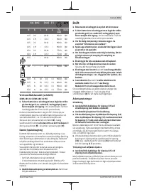
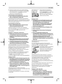
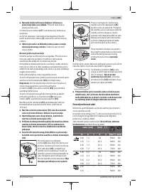
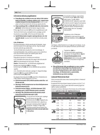
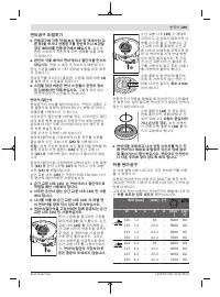
Adjust the position of the protective guard
(15)
to meet the
requirements of the operation. To do this, push the unlock-
ing lever
(1)
upward and rotate the protective guard
(15)
into the required position.
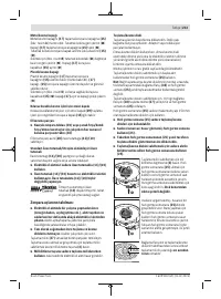
u
Always position the protective guard
(15)
such that
the two cams on the unlocking lever
(1)
engage in the
corresponding openings on the protective guard
(15).
u
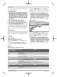
Adjust the protective guard
(15)
such that sparking in
the direction of the operator is prevented.
u
The protective guard
(15)
must only be able to be ro-
tated in the direction of the accessory while the un-
locking lever
(1)
is actuated. Otherwise, the power
tool must not be used any more under any circum-
stances and must be sent to the after-sales service.
Note:
The coding cams on the protective guard
(15)
ensure
that only a protective guard that is suitable for the power
tool can be fitted.
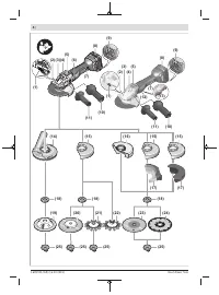
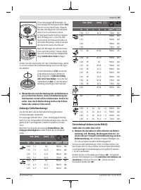
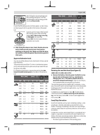
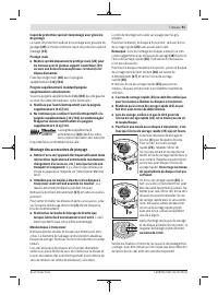
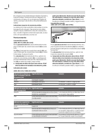
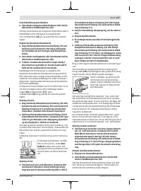
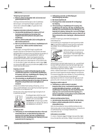
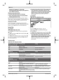
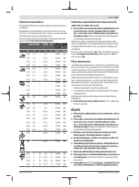
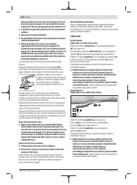
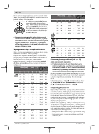
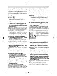
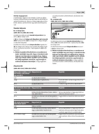
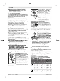
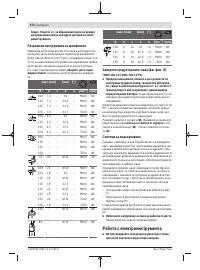
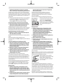
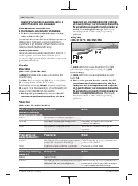
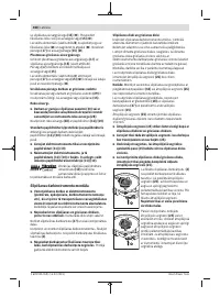
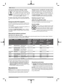
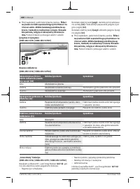
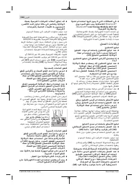
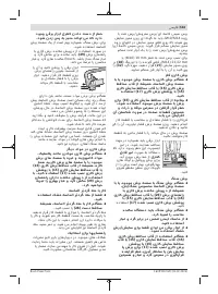
Extraction guard for sanding
For low-dust grinding of paints, lacquers and plastics in con-
junction with carbide grinding heads
(19)
, you can use the
extraction guard
(14)
. The extraction guard
(14)
is not suit-
able for machining metal.
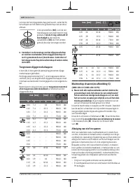
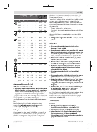
A suitable Bosch dust extractor can be connected to the ex-
traction guard
(14)
. To do so, insert the vacuum hose with
dust extraction adapter into the provided receiving connec-
tion of the extraction guard.
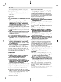
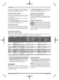
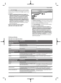
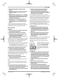
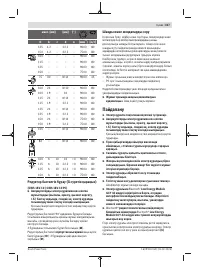
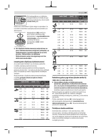
Protective guard for cutting
u
For cutting, always use the protective guard for
cutting
(16)
or the protective guard for grinding
(15)
together with the cover for cutting (17)
.
u
Provide sufficient dust extraction when cutting stone.
Bosch Power Tools
1 609 92A 769 | (13.02.2023)
Содержание
- 287 Сервис
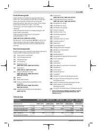
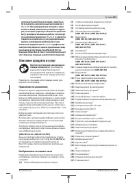
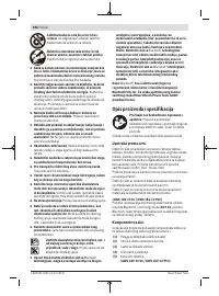
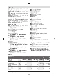
- 291 Описание продукта и услуг; Применение по назначению
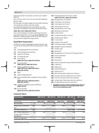
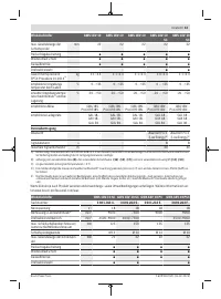
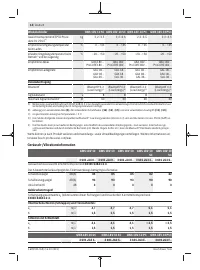
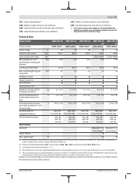
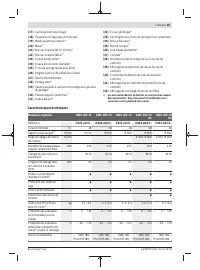
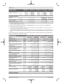
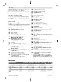
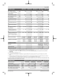
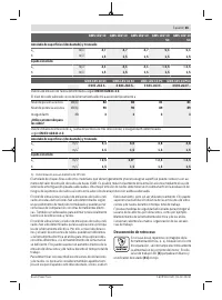
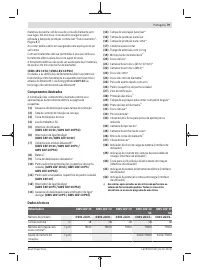
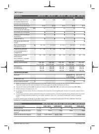
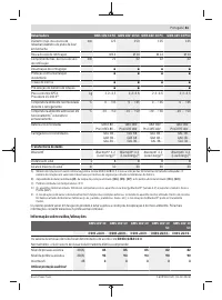
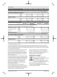
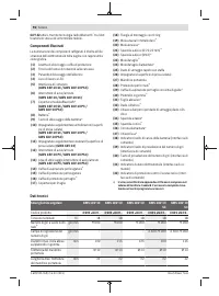
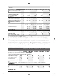
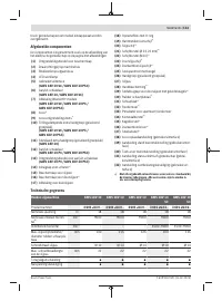
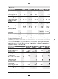
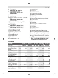
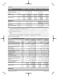
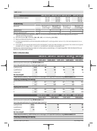
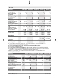
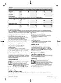
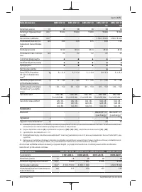
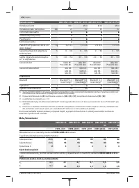
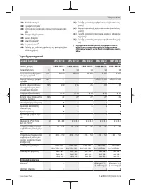
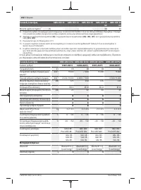
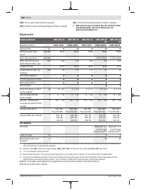
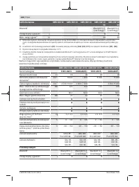
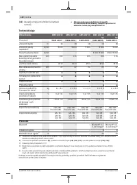
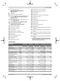
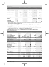
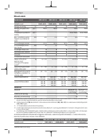
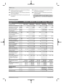
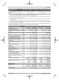
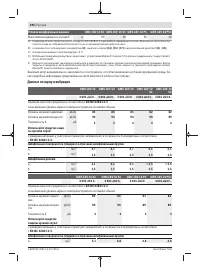
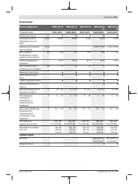
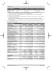
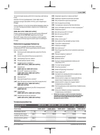
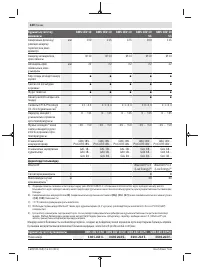
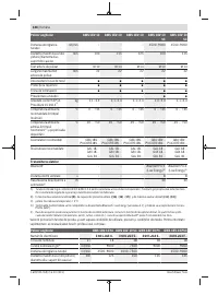
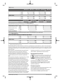
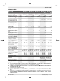
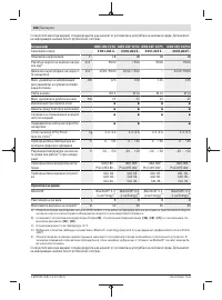
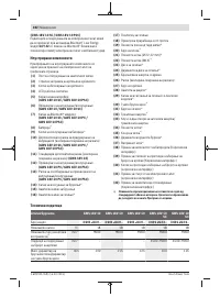
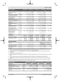
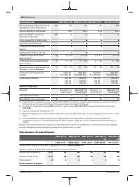
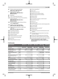
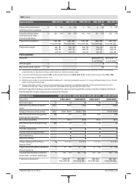
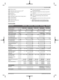
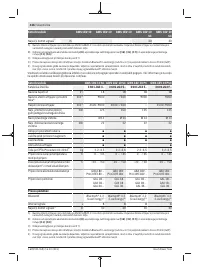
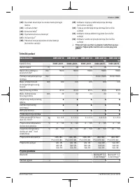
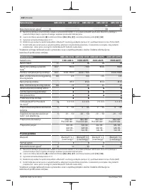
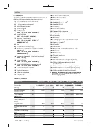
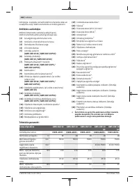
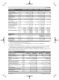
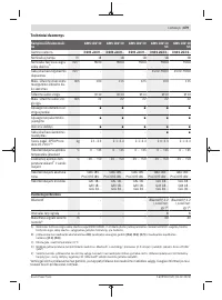
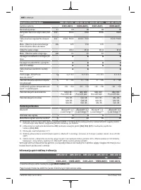
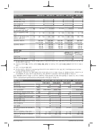
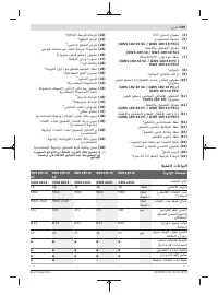
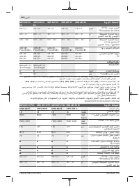
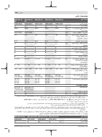
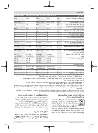
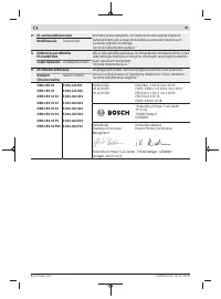
- 292 Технические данные
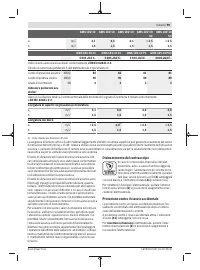
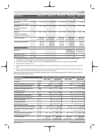
- 293 Угловая шлифовальная машина
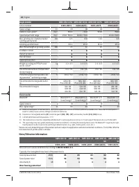
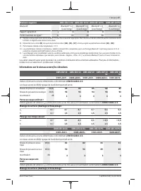
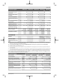
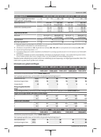
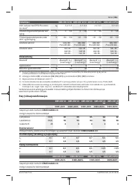
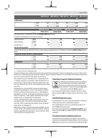
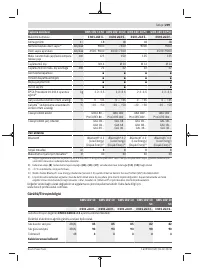
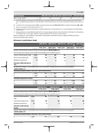
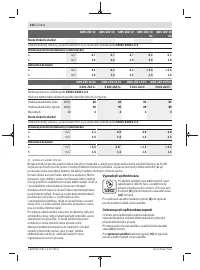
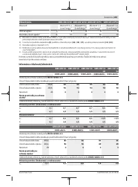
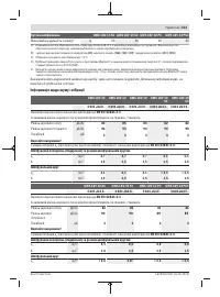
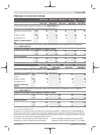
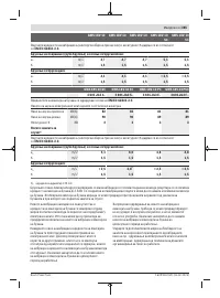
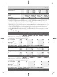
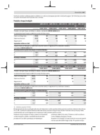
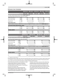
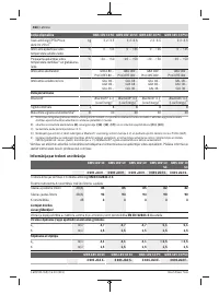
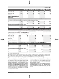
- 294 Данные по шуму и вибрации
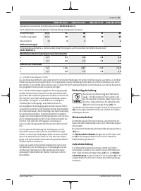
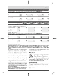
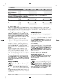
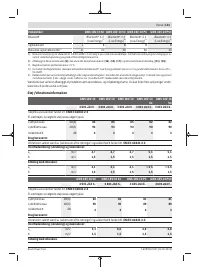
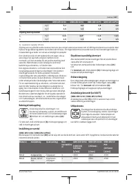
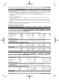
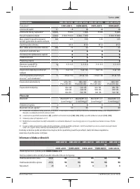
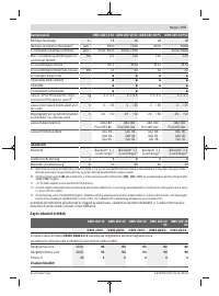
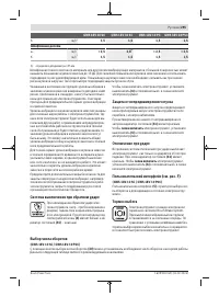
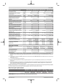
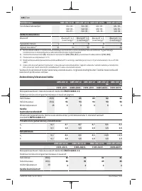
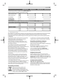
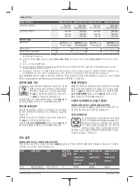
- 295 Шлифование диском; Система выключения при обратном ударе; Отключение при ударе; снова включить; Тормоз выбега
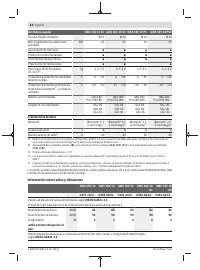
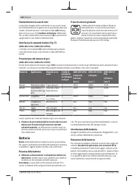
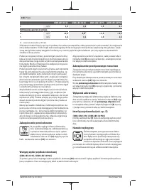
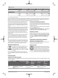
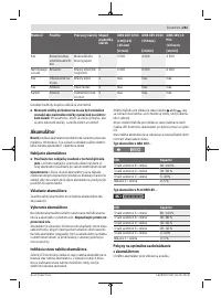
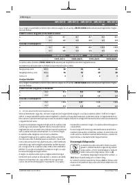
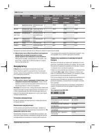
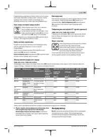
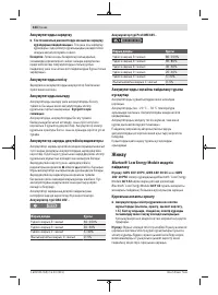
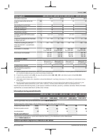
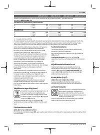
- 296 Аккумулятор; Зарядка аккумулятора; Не
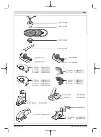
- 297 Сборка; Установка модуля; Монтаж защитных устройств
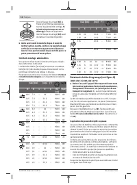
- 298 Монтаж шлифовальной оснастки
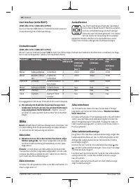
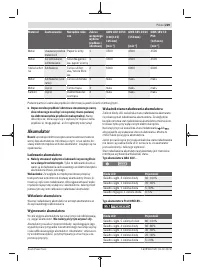
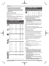
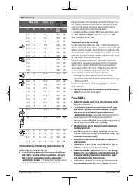
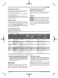
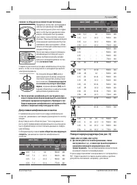
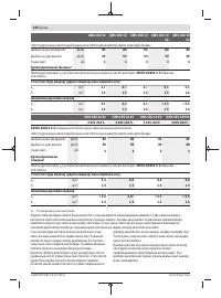
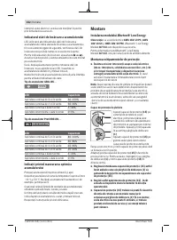
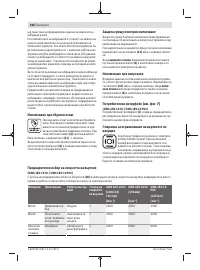
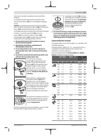
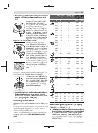
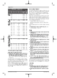
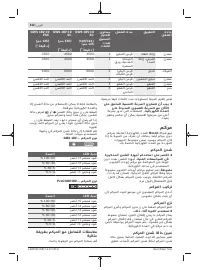
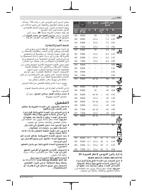
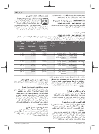
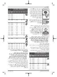
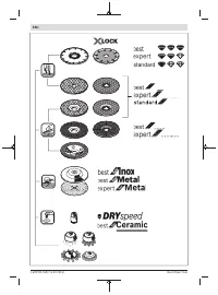
- 299 Допустимая шлифовальная оснастка; число оборотов или окружную
- 300 Удаление пыли и стружки; Работа с инструментом; Указания по применению
- 302 Включение электроинструмента; Решение
- 303 Техобслуживание и сервис; Техобслуживание и очистка; Россия
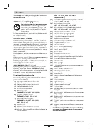
- 304 Українська; Вказівки з техніки безпеки; ДЖЕННЯ; електроінструментом.
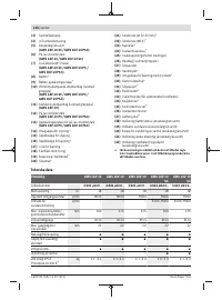
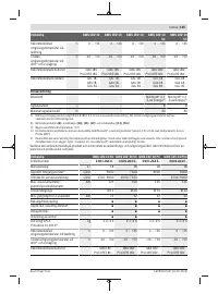
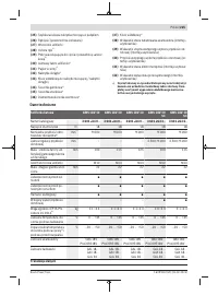
Характеристики

Остались вопросы?Не нашли свой ответ в руководстве или возникли другие проблемы? Задайте свой вопрос в форме ниже с подробным описанием вашей ситуации, чтобы другие люди и специалисты смогли дать на него ответ. Если вы знаете как решить проблему другого человека, пожалуйста, подскажите ему :)


