Магнитолы Pioneer MVH-X560BT - инструкция пользователя по применению, эксплуатации и установке на русском языке. Мы надеемся, она поможет вам решить возникшие у вас вопросы при эксплуатации техники.
Если остались вопросы, задайте их в комментариях после инструкции.
"Загружаем инструкцию", означает, что нужно подождать пока файл загрузится и можно будет его читать онлайн. Некоторые инструкции очень большие и время их появления зависит от вашей скорости интернета.


9
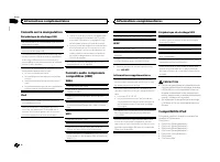
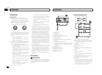
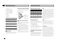
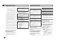
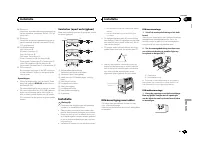
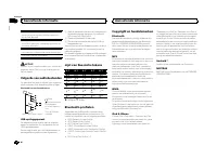
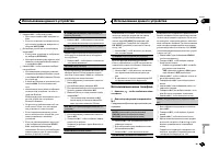
Blue/white
The pin position of the ISO connector will dif-
fer depending on the type of vehicle. Connect
9
and
b
when Pin 5 is an antenna control
type. In another type of vehicle, never con-
nect
9
and
b
.
a
Blue/white
Connect to system control terminal of the
power amp (max. 300 mA 12 V DC).
b
Blue/white
Connect to auto-antenna relay control termi-
nal (max. 300 mA 12 V DC).
c
Speaker leads
White: Front left
+
White/black: Front left
*
Gray: Front right
+
Gray/black: Front right
*
Green: Rear left
+
or subwoofer
+
Green/black: Rear left
*
or subwoofer
*
Violet: Rear right
+
or subwoofer
+
Violet/black: Rear right
*
or subwoofer
*
d
ISO connector
In some vehicles, the ISO connector may be
divided into two. In this case, be sure to con-
nect to both connectors.
Notes
!
Change the initial menu of this unit. Refer to
The subwoofer output of this unit is monau-
ral.
!
When using a subwoofer of 70 W (2
W
), be
sure to connect the subwoofer to the violet
and violet/black leads of this unit. Do not
connect anything to the green and green/
black leads.
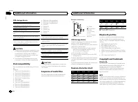
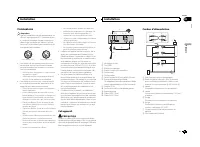
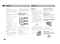
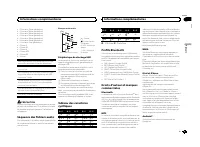
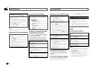
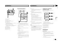
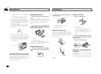
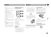
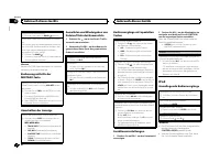
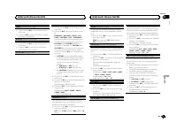
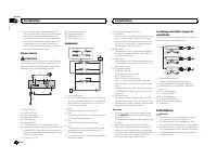
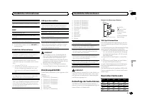
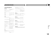
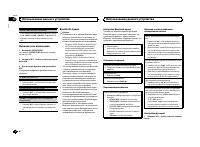
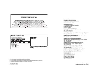
Power amp (sold separately)
Perform these connections when using the op-
tional amplifier.
1
1
3
2
4
5
5
3
2
6
7
7
1
3
2
8
9
9
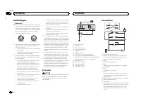
1
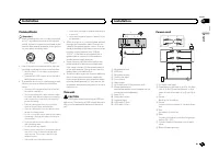
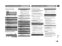
System remote control
Connect to Blue/white cable.
2
Power amp (sold separately)
3
Connect with RCA cables (sold separately)
4
To Rear output
5
Rear speaker
6
To Front output
7
Front speaker
8
To Subwoofer output
9
Subwoofer
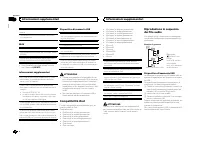
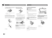
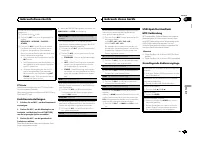
Installation
Important
!
Check all connections and systems before
final installation.
!
Do not use unauthorized parts as this may
cause malfunctions.
!
Consult your dealer if installation requires
drilling of holes or other modifications to the
vehicle.
!
Do not install this unit where:
—
it may interfere with operation of the vehicle.
—
it may cause injury to a passenger as a result
of a sudden stop.
!
The semiconductor laser will be damaged if
it overheats. Install this unit away from hot
places such as near the heater outlet.
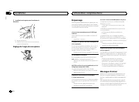
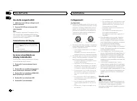
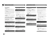
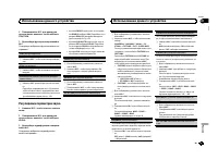
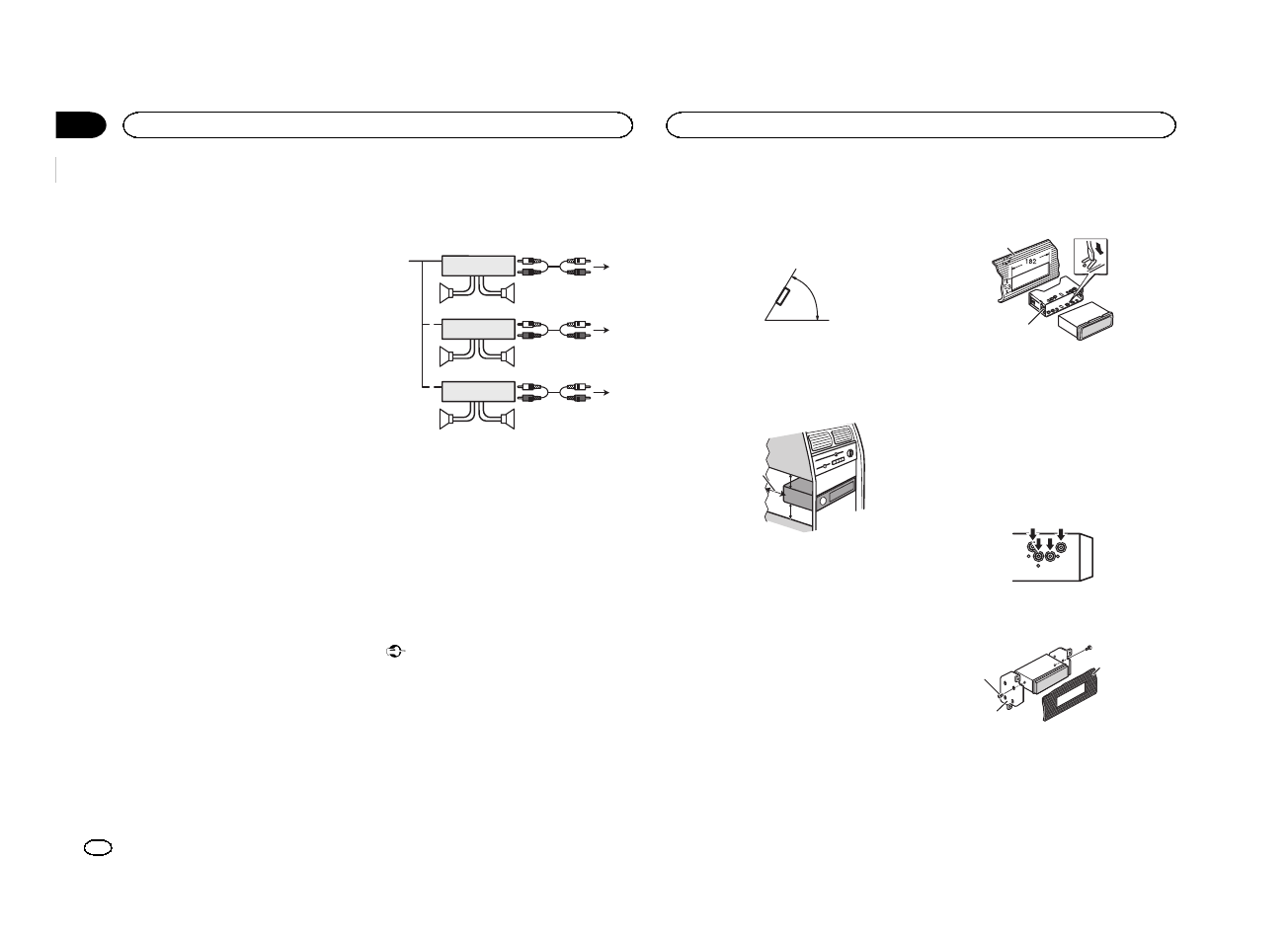
!
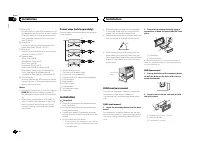
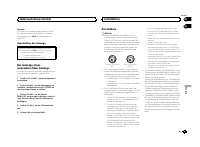
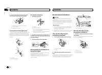
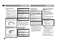
Optimum performance is obtained when the
unit is installed at an angle of less than 60°.
60°
!
When installing, to ensure proper heat dis-
persal when using this unit, make sure you
leave ample space behind the rear panel and
wrap any loose cables so they are not block-
ing the vents.
5cm
cm
Leave ample
space
5 cm
5 cm
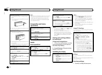
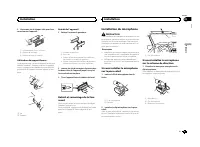
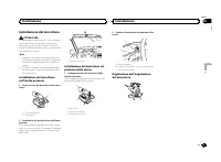
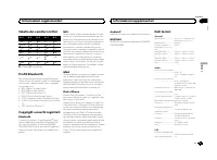
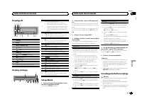
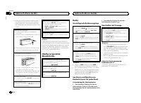
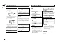
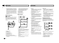
DIN front/rear mount
This unit can be properly installed using either
front-mount or rear-mount installation.
Use commercially available parts when instal-
ling.
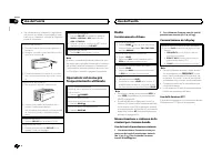
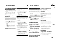
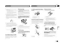
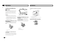
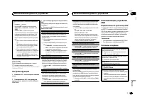
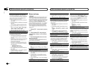
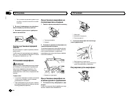
DIN Front-mount
1
Insert the mounting sleeve into the dash-
board.
For installation in shallow spaces, use the sup-
plied mounting sleeve. If there is enough space,
use the mounting sleeve that came with the ve-
hicle.
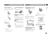
2
Secure the mounting sleeve by using a
screwdriver to bend the metal tabs (90°) into
place.
1
2
1
Dashboard
2
Mounting sleeve
#
Make sure that the unit is installed securely in
place. An unstable installation may cause skipping
or other malfunctions.
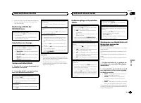
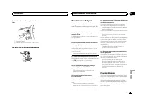
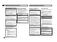
DIN Rear-mount
1
Line up the holes on the mounting brack-
et with the holes on the sides of the unit to
attach the bracket.
2
Screw in one screw on each side to hold
the unit in place.
1
2
3
1
Tapping screw (5 mm × 8 mm)
2
Mounting bracket
3
Dashboard or console
Installation
16
Section
Installation
En
03
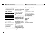
Содержание
- 138 Благодарим Вас; PIONEER; Держите данное; Сведения об этом устройстве; RDS; ПРЕДУПРЕЖДЕНИЕ; Pioneer CarStereo-Pass; При возникновении проблем; Перед началом эксплуатации
- 139 Установочное меню; SET UP; YES; Меню системы; SRC; Использование данного устройства
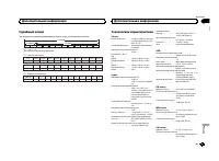
- 140 Радиоприемник; Основные операции; SEEK; AF; AF; FREQUENCY; Использование функций
- 141 PTY; Настройка функций; FUNCTION; Запоминающее устройство; Подключение по протоколу
- 142 Функции кнопки
- 144 CONTROL iPod; Для пользователей
- 145 Для пользователей смартфонов; iPhone; Настройки для громкой связи
- 146 Использование меню соединения
- 147 DEL DEVICE; Использование меню телефона; Нажмите
- 148 Функции и их назначение; аудио; Настройка
- 149 Регулировки параметров звука; AUDIO
- 150 PW SAVE; DIMMER
- 151 Выбор цвета подсветки; Меню функции подсветки; Настройка цвета подсветки
- 152 Меню; Стартовое меню
- 153 Меню систе; AUX; Соединения; Установка
- 154 Данное устройство; ВНИМАНИЕ; Шнур питания; Примечания; на; Усилитель мощности
- 155 Переднее; DIN
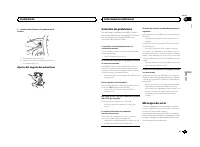
- 156 Установка микрофона; Регулировка угла микрофона
- 157 Общие; Дополнительная информация
- 159 Поддержка
- 160 Профили
- 162 Примечание


