Котел котёл Baxi SLIM HPS 1.80 A7114600 - инструкция пользователя по применению, эксплуатации и установке на русском языке. Мы надеемся, она поможет вам решить возникшие у вас вопросы при эксплуатации техники.
Если остались вопросы, задайте их в комментариях после инструкции.
"Загружаем инструкцию", означает, что нужно подождать пока файл загрузится и можно будет его читать онлайн. Некоторые инструкции очень большие и время их появления зависит от вашей скорости интернета.

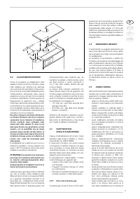
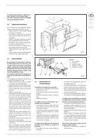
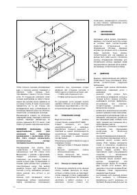
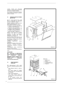

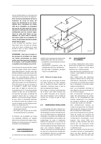
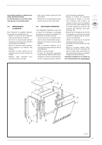

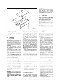


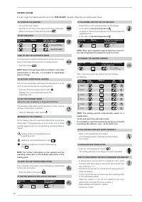


with the screws provided;
– insert two 3/4” pipes in the holes in the
brackets, lif t the boiler carefully and place
into position.
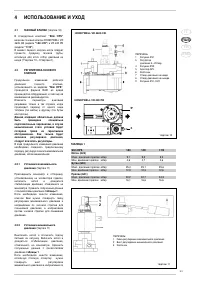
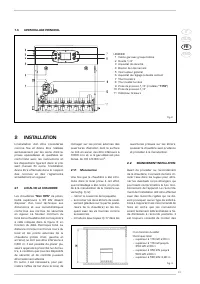
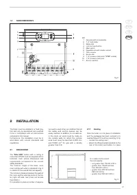
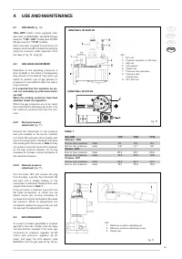
2.2
CONNECTING
UP SYSTEM
Before proceeding to connect up the boi-
ler, you are recommended to make the
water circulating in the piping in order to
eliminate any foreign bodies that might be
detrimental to the operating efficiency of
the appliance.
The unit must be connected up with rigid
pipe fittings which will not subject it to
stress of any kind.
The connections should be easy to discon-
nect using pipe unions with orientable con-
nections. You are recommended to install
suitable shutoff valves on the system flow
and return pipes.
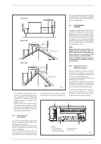
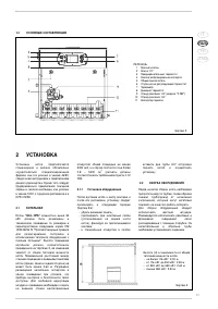
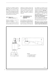
In order to achieve a good water distribu-
tion inside the cast-iron body, the system
flow and return pipes should be connec-
ted to the same side of the boiler.
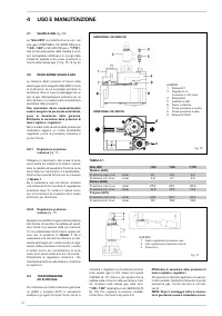
The boiler comes supplied standard with
the attachments on the right-hand side,
with the possibility of them being tran-
sferred to the left-hand side.
In that case, move the water distributor,
located on the return header, and the
thermostat bulbs located in the sheathe,
to the same side.
The thermal jump between the system flow
and return pipes should not exceed 20°C.
For this purpose, it is advisable to install a
mixer valve with corresponding anti-conden-
sation pump.
CAUTION: The system circulation pump or
pumps must go into action at the time of
boiler ignition.
For this purpose, you are recommended
to use an automatic system of prece-
dence.
The gas connection must be made using
seamless steel pipe (Mannesmann type),
galvanized and with threaded joints provi-
ded with gaskets, excluding three-piece con-
nections, except for initial and end connec-
tions. Where the piping has to pass through
walls, a suitable insulating sleeve must be
provided.
When sizing gas piping, from the meter to
the boiler, take into account both the volume
flow rates (consumption) in m
3
/h and the
relative density of the gas in question. The
sections of the piping making up the system
must be such as to guarantee a supply of
gas suf ficient to cover the maximum
demand, limiting pressure loss between the
gas meter and any apparatus being used to
not greater than:
– 1.0 mbar for family II gases (natural gas);
– 2.0 mbar for family III gases (butane or
propane).
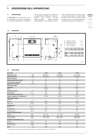
An adhesive data plate is sticked inside the
front panel; it contains all the technical data
identifying the boiler and the type of gas for
which the boiler is arranged.
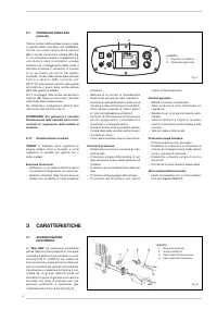
2.3
CHARACTERISTICS
OF FEEDWATER
It is absolutely essential that the water used
for the central heating system should be
treated in the following cases:
– Very extensive systems (with high con-
tents of feedwater).
– Frequent addition of makeup water into
the system.
– S h o u l d i t b e n e c e s s a r y t o e mp t y t h e
system either partially or totally.
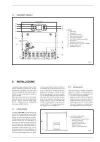
2.3.1
Filter on the gas pipe
The gas valve is supplied ex factory with an
inlet filter, which, however, is not adequate
to entrap all the impurities in the gas or in
gas main pipes.
To prevent malfunctioning of the valve, or in
certain cases even to cut out the safety
device with which the valve is equipped,
install an adequate filter on the gas pipe.
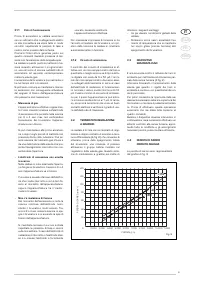
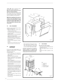
2.4
SYSTEM FILLING
Filling must be done slowly so as to allow
any air bubbles to be bled off through the air
vents provided on the heating system.
The pressure of cold charging of the
system, and the pressure of pre-pressuri-
zation of the expansion vessel, must corre-
spond, or in any case must not be less than,
the height of the static column of the
system (e.g., for a static column of 5 m, the
pre-pressurization pressure of the expan-
sion vessel and the charging pressure must
correspond to at least 0.5 bar).
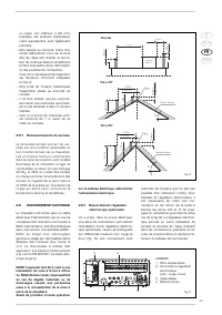
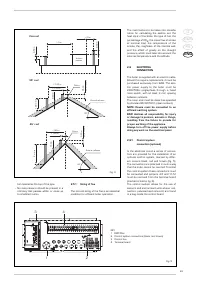
2.5
CONNECTING
UP FLUE
The flue for the atmospherical expulsion of
the combustion products from natural
draught appliances must meet the following
requirements:
– Be gas-tight to the combustion products,
waterproof and thermally insulated.
– Be built of mat erials suit able for keep
resisting to normal mechanical stresses,
heat, and the action of combustion pro-
ducts and their possible condensates.
– Follow a ver tical path and not present
a n y t h r o t t l i n g t h r o u g h o u t i t s e n t i r e
length.
– Be adequately insulated to prevent phe-
nomena of condensation or smokes coo-
ling, in par ticular if located outside the
building or in unheated ambiences.
– Be se t at an adequat e dis t ance fr om
combustible or easily inflammable mate-
rial by means of an air gap or suitable
insulating material.
– H a v e b e n e a t h t h e m o u t h o f t h e f i r s t
smoke duct a chamber f or collecting
solid material and any condensate; the
height of the chamber must be at least
500 mm.
Access to the chamber must be guaran-
teed by means of an opening provided
with an air-tight metal door.
– Have a circular, square, or rectangular
int er nal cr oss section; in t he case of
square or rectangular sections, the cor-
ners must be rounded off with a radius
o f n o t l e s s t h a n 2 0 m m . H o w e v e r,
hydraulically equivalent cross sections
are allowed.
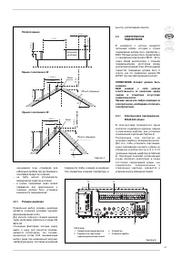
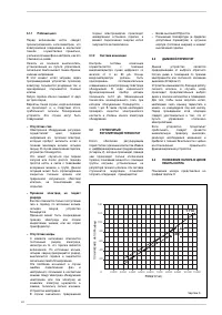
– Be equipped with a chimney-pot at the
top, which must be outside the so-called
back-flow zone, so as to prevent the for-
mation of back-flow, which prevents free
discharge of the products of combustion
into the atmosphere.
Therefore, conform to the minimum hei-
ghts indicated in fig. 4.
– Be devoid of mechanical means of suc-
48
Fig. 3/a


