
Измерительные приборы Bosch 0.601.015.200 - инструкция пользователя по применению, эксплуатации и установке на русском языке. Мы надеемся, она поможет вам решить возникшие у вас вопросы при эксплуатации техники.
Если остались вопросы, задайте их в комментариях после инструкции.
"Загружаем инструкцию", означает, что нужно подождать пока файл загрузится и можно будет его читать онлайн. Некоторые инструкции очень большие и время их появления зависит от вашей скорости интернета.

20
| English
1 609 92A 0L0 | (16.5.14)
Bosch Power Tools
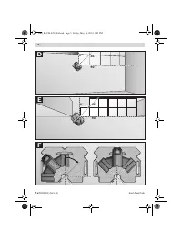
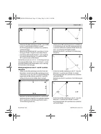
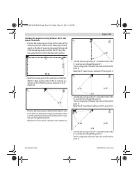
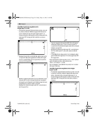
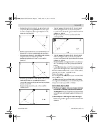
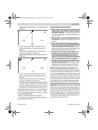
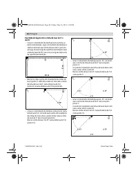
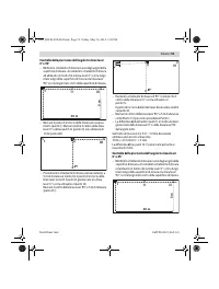
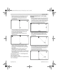
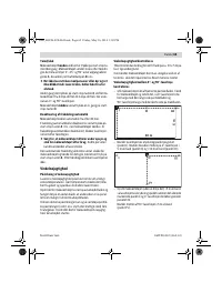
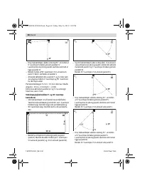
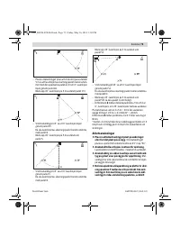
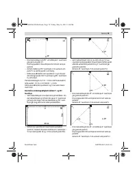
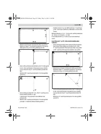
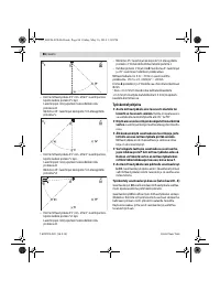
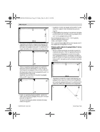
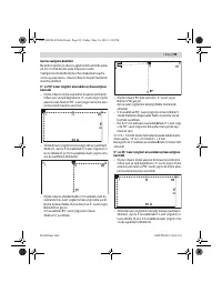
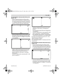
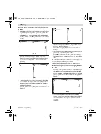
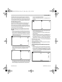
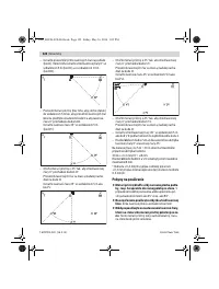
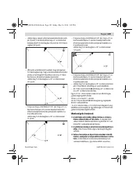
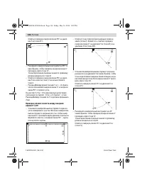
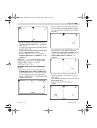
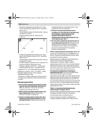
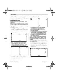
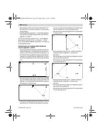
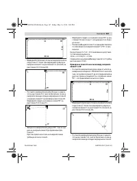
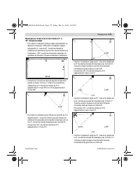
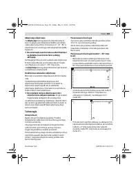
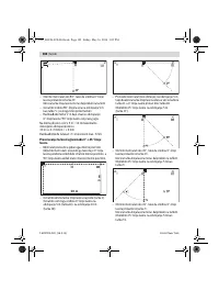
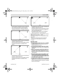
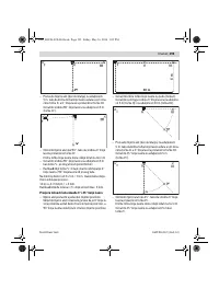
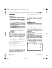
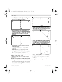
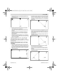
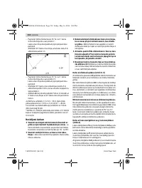
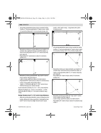
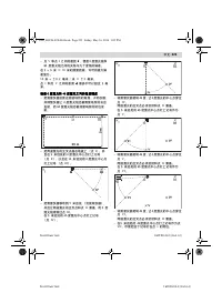
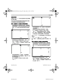
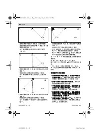
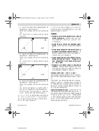
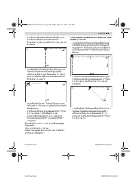
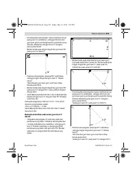
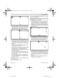
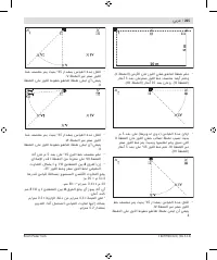
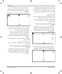
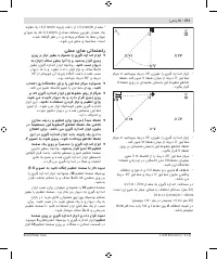
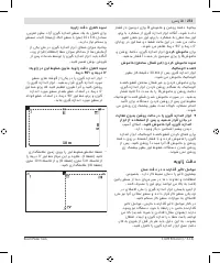
– Mark the centre of the 45 ° laser line at a distance of
5 m as point
VII
as near as possible next to the point
I
.
– The difference
d
of the two points
VII
and
I
is the actu-
al deviation of the 0 ° laser line and the 45 ° laser line.
The measuring length 4 x 5 m = 20 m has a maximum
admissible deviation of: 20 m x ±
0.4 mm/m* = ± 8 mm.
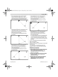
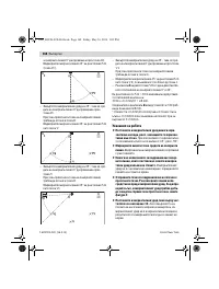
Therefore, the maximum difference
d
between the points
I
and
VII
may be 8 mm or less.
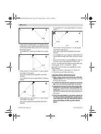
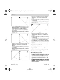
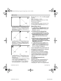
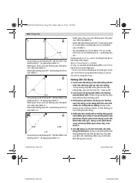
* The value ± 0,4 mm/m results from the angle accuracy
±
0.2 mm/m plus a possible uncertainty of 0.2 mm/m
while turning.
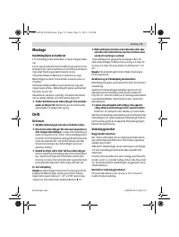
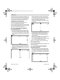
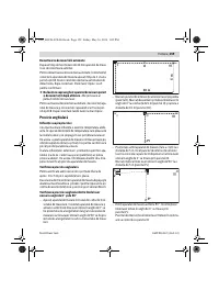
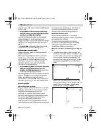
Working Advice
Always position the measuring tool flat on the floor
or fix it flat on the wall.
In case of uneven positioning
or fixing, the angle is smaller than 45 ° and 90 °.
Always use the centre of the laser line for marking.
The width of the laser line changes with the distance.
Never use the laser lines that the measuring tool
standing on the floor projects on the wall for align-
ment.
The measuring tool is not self-levelling. There-
fore, the line on the wall is distorted.
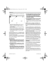
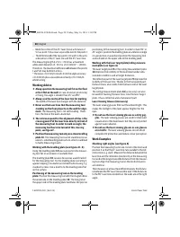
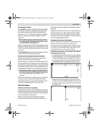
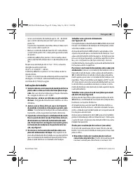
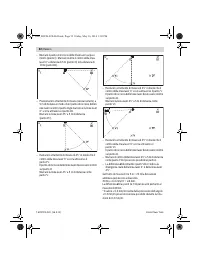
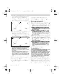
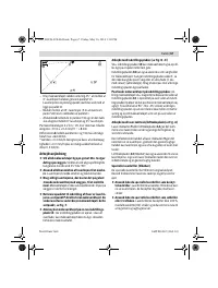
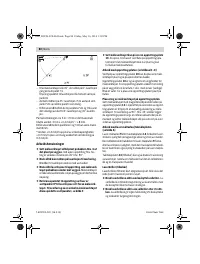
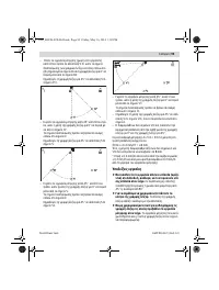
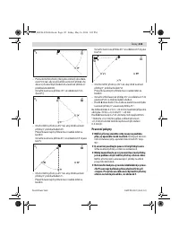
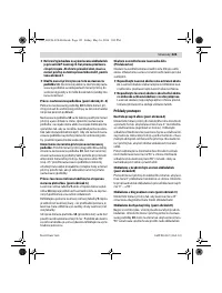
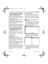
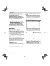
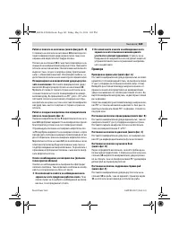
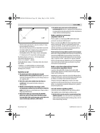
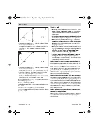
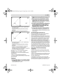
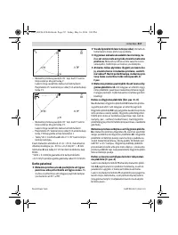
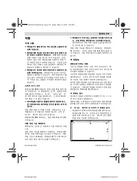
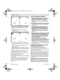
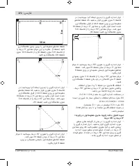
The reference point for the alignment of tiles is the
crossing point P of the laser lines directly in front of
the measuring tool. In order to mark an angle, the
measuring tool has to be turned at this crossing
point, see figure F.
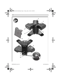
Position the measuring tool only on a clean levelling
plate 10.
The measuring tool cannot stand level on an
uneven, soiled levelling plate surface, which could lead
to faulty measuring results.
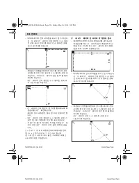
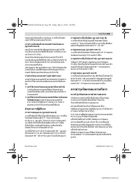
Working with the levelling plate (see figures D – E)
Using the levelling plate
10
you can position the measur-
ing tool flat on an uneven or unstable floor.
The levelling plate
10
can also be used as a wall bracket
for the measuring tool. Fix the levelling plate (securing it
against slipping) on a wall or an inclined surface using e. g.
standard screws. Use a level to fix the levelling plate flat
on the surface.
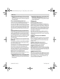
Positioning of the measuring tool on the levelling
plate:
Position the measuring tool with the magnets
4
on
the underside on the levelling plate
10
. The line grid on
the upper side of the levelling plate facilitates the precise
positioning of the measuring tool. In order to mark 90 ° or
45 ° angles, position the levelling plate at a reference edge
or a projection on a wall and position the measuring tool
as illustrated on the upper side of the levelling plate.
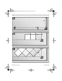
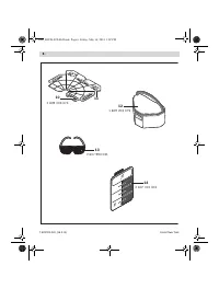
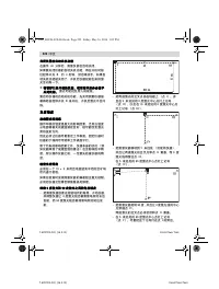
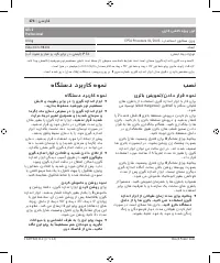
Working with the laser target plate/ceiling measure-
ment plate (see figure A)
The laser target plate
9
or the ceiling measurement plate
14
improves the visibility of the laser beam under unfa-
vourable conditions and at longer distances.
The reflective part of the laser target plate
9
improves the
visibility of the laser line. Thanks to the transparent part,
the laser line is also visible from the back side of the laser
target plate.
The ceiling measurement plate
14
(accessory) can also
be used for marking the laser lines. Like the laser target
plate, it has a reflective and a transparent part.
Laser Viewing Glasses (Accessory)
The laser viewing glasses filter out the ambient light. This
makes the red light of the laser appear brighter for the
eyes.
Do not use the laser viewing glasses as safety gog-
gles.
The laser viewing glasses are used for improved
visualisation of the laser beam, but they do not protect
against laser radiation.
Do not use the laser viewing glasses as sun glasses
or in traffic.
The laser viewing glasses do not afford
complete UV protection and reduce colour perception.
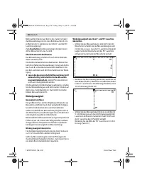
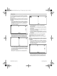
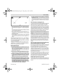
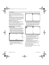
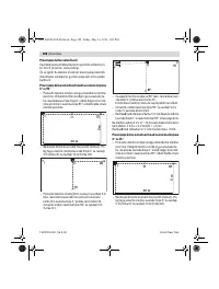
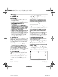
Work Examples
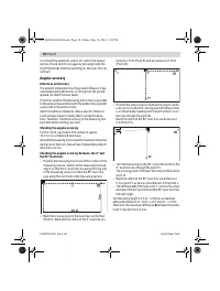
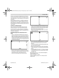
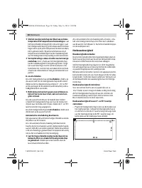
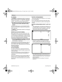
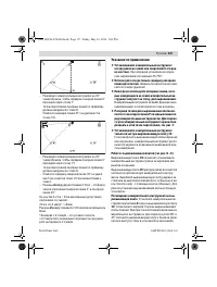
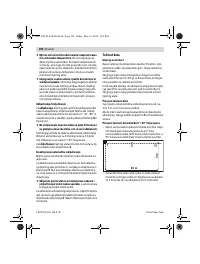
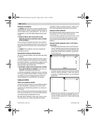
Checking right angles (see figure A)
Position the measuring tool in one corner of the room and
position it so that the 0 ° laser line runs parallel to the ref-
erence line (e. g. wall). Measure the distance between the
laser line and the reference line directly at the measuring
tool and at the longest possible distance from the measur-
ing tool. Align the measuring tool so that both distances
are identical.
Then measure at at least two different points the distanc-
es between the 90 ° laser line and the wall. If the distances
to the 90 ° laser line are identical, the walls are at the right
angle.
OBJ_BUCH-828-004.book Page 20 Friday, May 16, 2014 1:02 PM
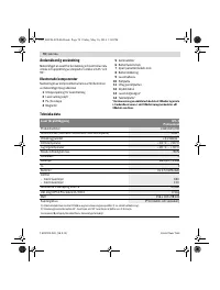
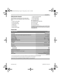
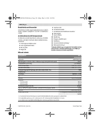
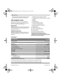
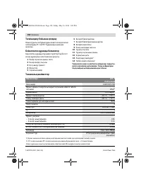
Содержание
- 133 чувствительных к магнитному полю.; Описание продукта и услуг; Применение по назначению; Лазер для плитки
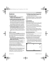
- 134 Сборка; Установка/замена батареек; Работа с инструментом; Эксплуатация; включения
- 135 выключения; Угловая точность; Факторы, влияющие на точность
- 137 Указания по применению
- 138 Примеры возможных видов работы; Техобслуживание и сервис; Техобслуживание и очистка
- 139 Россия; Беларусь; Утилизация
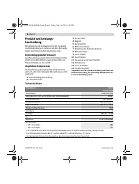
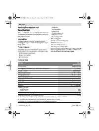
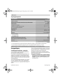
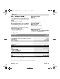
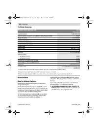
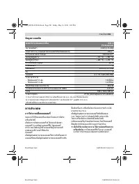
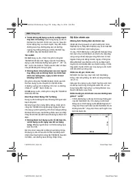
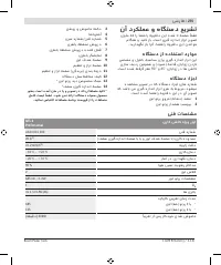
Характеристики

Остались вопросы?Не нашли свой ответ в руководстве или возникли другие проблемы? Задайте свой вопрос в форме ниже с подробным описанием вашей ситуации, чтобы другие люди и специалисты смогли дать на него ответ. Если вы знаете как решить проблему другого человека, пожалуйста, подскажите ему :)


