Сварочное оборудование Awelco BLUEMIG 170 - инструкция пользователя по применению, эксплуатации и установке на русском языке. Мы надеемся, она поможет вам решить возникшие у вас вопросы при эксплуатации техники.
Если остались вопросы, задайте их в комментариях после инструкции.
"Загружаем инструкцию", означает, что нужно подождать пока файл загрузится и можно будет его читать онлайн. Некоторые инструкции очень большие и время их появления зависит от вашей скорости интернета.

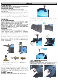


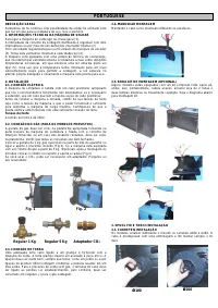
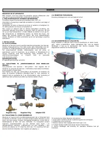
3.2. WIRE-FEEDER MOTOR
Make sure that the size of the groove in the feed roll corresponds to the
welding wire size being used. The feed roll has the wire diameter
stamped on its side. The machines are equipped with proper shagreneed
rolls suitable for welding with flux cored wire without gas protection. T o
weld with full wire with GAS protection you have to replace the roll of the
wire feeder group which has
V
form for the steel wire and
U
form for the
aluminium wire. If you intend to use the welder with gas protection you
have to require such rolls and the pressure reducer to your retailer or to
the builder society.
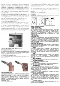
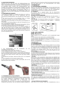
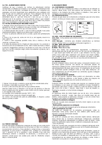
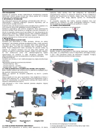
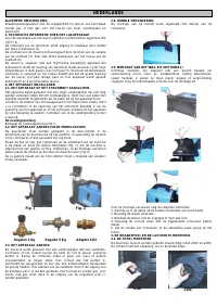
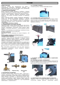
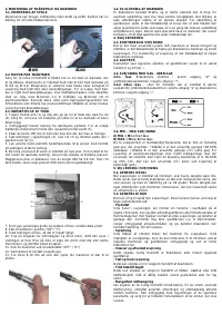
3.3. FEEDING WIRE INTO THE WELDING TORCH
1. Release the Spring Loaded Pressure Arm (1) rotate the Idle Roll Arm
(2) away from the W ire Feed Drive Roll (3). Ensure that the groove size
in the feeding position on the drive roll matches the wire size being used.
2. Carefully detach the end of the wire from the spool. To prevent the
spool from unwinding, maintain tension on the wire until after step 5.
3. Cut the bent portion of wire off and straighten the first 10 cm.
4. Thread the wire through the ingoing guide tube (4), over the drive roll
(3), and into the outgoing guide tube (5).
5. Close the idle roll arm and latch the spring loaded pressure arm (2) in
place. Rotate the spool counterclockwise if required to take up extra
slack in the wire.
6. The idle roll pressure adjustment wing nut is normally set for mid-
position on the pressure arm threads. If feeding problems occur because
the wire is flattened excessively, turn the pressure adjustment counter-
clockwise to reduce distortion of the wire. Slightly less pressure may be
required when using 0,6 mm wire. If the drive roll slips while feeding wire,
the pressure should be increased until the wire feeds properly.
7. Remove gas nozzle and contact tip from end of gun.
8. Turn the machine ON (“I”).
9. Straighten the gun cable assembly.
10. Depress the gun trigger switch and feed welding wire through the gun
and cable. (Point gun away from yourself and others while feeding wire.)
Release gun trigger after wire appears at end of gun.
11. Turn the machine OFF (“O”).
12. Replace contact tip and gas nozzle.
13. Cut the wire off 6 – 10 mm from the end of the tip. The machine is
now ready to weld.
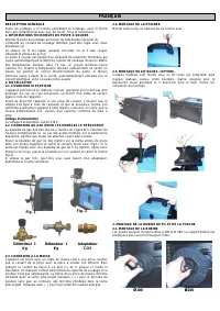
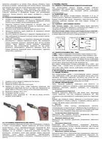
3.4. TORCH CONNECTION
The torch is connected directly to the welding machine so it is ready for
use. A probable replacement of the torch must be done with care and if
possible by a technician. To replace contact tips, it is necessary t o
unscrew or to pull it. Replace tip, check that it corresponds with the wir e
size and replace the gas shroud. For good wire feeding during welding
operations, it is essential that the correct size parts are used for each
wire. Keep always clean the contact tip.
4. WELDING MODE
4.1. CONTINUOUS WELDING
It is the mode in which the welding machine is likely to be used the most.
In this mode, you have only to press the button of the torch and the
welding machine begins to work. To stop welding it is necessary
releasing the torch button.
4.2. G AS PRESSURE
Gas pressure should normally be set to give a reading between 6 / 12
litres per minute on the flowmeter. Anyway, every operator will find what
suits him the most with his type of work and can make the necessary
adjustment.
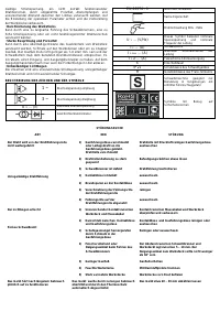
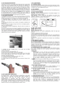
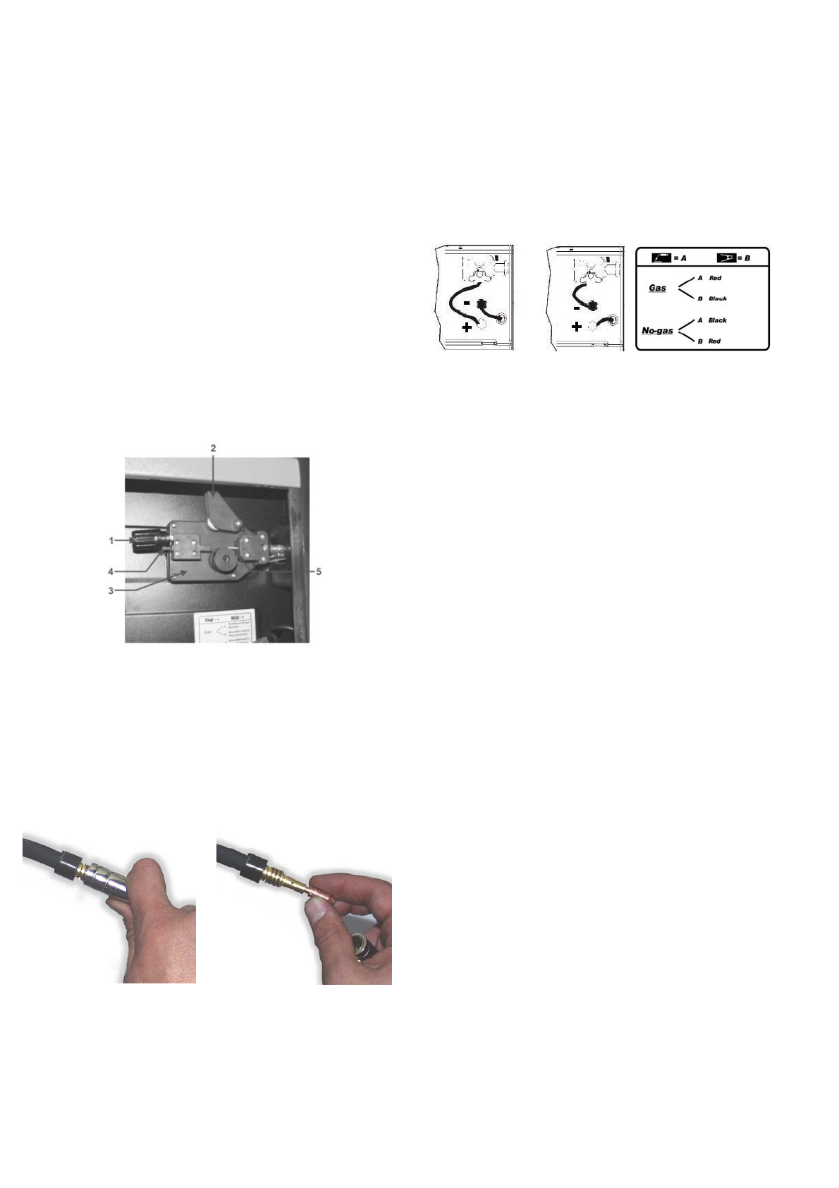
4.3. G AS – NO GAS WELDING MODE
4.3.1. Gas
- Connect torch clamp to positive terminal “+” and earth clamp
to negative(-)
4.3.2. No gas
- (only for preset models) Connect earth clamp to positive
terminal (+) and the torch clamp to negative (-).
4.4. MIG - MAG WELDING MODE
A ) MIG
=
M
etal
I
nert
G
as
B ) M AG
=
M
etal
A
ctive
G
as
These two modes are perfectly equivalent, the difference is given by the
kind of gas you use. In case A the gas employed is ARGON ( inert gas).
In case B the gas employed is CO
2
( active gas). To weld alluminium
alloys you need use ARGON (100%), to weld steel it is enough a
compound of ARGON 80% and CO
2
20%. You can only use CO
2
in cas e
you will weld iron.
5. WELDING GUIDE
5.1. GENERAL RULE
W hen welding on the lowest output settings, it is necessary to keep the
arc as short as possible. This should be achieved by holding welding
torch as close as possible and at an angle of approximately 60 degrees
to the workpiece. The arc length can be increased when welding on the
highest settings, an arc length up to 20 mm can be enough when welding
on maximum settings.
5.2. GENERAL WELDING TIPS
From time to time, some faults may be observed in the weld owing t o
external influences rather due to welding machine’s faults. Here ar e
some that you may come across :
· Porosity
Small holes in the weld, caused by break-down in gas coverage of the
weld or sometimes by foreign bodies inclusion. Remedy is, usually, to
grind out the weld. Remember, check before the gas flux (about 8
liters/minutes), clean well the working place and finally incline the torch
while welding.
· Spatter
Small balls of molten metal which come out of the arc. A little quantity is
unavoidable, but it should be kept down to a minimum by selecting
correct settings and having a correct gas flow and by keeping the welding
torch clean.
·
Narrow heap w elding
Can be caused by moving the torch too fast or by an incorrect gas flow.
·
Very thick or w ide w elding
Can be caused by moving the torch too slowly.
·
Wire burns back
It can be caused by wire feed slipping, loose or damaged welding tip,
poor wire, nozzle held too close to work or voltage too high.
· Little
penetration
It can be caused by moving torch too fast, too low voltage setting or
incorrect feed setting, reversed polarity, insufficient blunting and distance
between strips. Take care of operational parameters adjustment and
improve the preparation of the workpieces.
· Workpiece’s
piercing
It may be caused by moving the welding torch too slow, too high welding
power or by an invalid wire feeding.
·
Heavy spatter and porosity
It can be caused by nozzle too far from work, dirt on work or by low gas
flow. You have to the two parameters, remeber that gas has not to be
lower than 7-8 liters/ min. and that the current of welding is appropriated
to the wire you are using. It is advisable to have a pressure reducer of
input and output. On the manom eter you can read the range expressed
in liter.
·
Welding arc instability
It may be caused by an insufficient welding voltage, irregular wire feed,
insufficient protective welding gas.

