
Водонагреватели ELDOM Green Line FV20060S - инструкция пользователя по применению, эксплуатации и установке на русском языке. Мы надеемся, она поможет вам решить возникшие у вас вопросы при эксплуатации техники.
Если остались вопросы, задайте их в комментариях после инструкции.
"Загружаем инструкцию", означает, что нужно подождать пока файл загрузится и можно будет его читать онлайн. Некоторые инструкции очень большие и время их появления зависит от вашей скорости интернета.
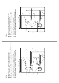
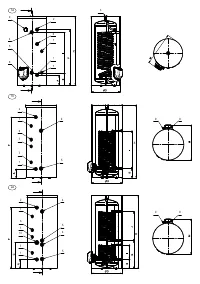


separate safety and non-return valves.
W
ater heater connection to the water supply network is shown on
Fig 3. There water heater works at the water supply network
pressure and that of the safety valve. If the water mains pressure is
greater than 0,5 MPa a reduce valve (pressure-reducing valve)
have to be installed.
W
hen the water heater is part of a system providing hot water it
usually works at a lower pressure that the pressure in the water
supply network, and for its connection additional fittings are
installed. We recommend these connections to be completed in
accordance with Fig. 4. The competent installation company shall
identify and provide the necessary additional fittings. This is not a
manufacturer and/or seller liability, and is not subject to warranty
service.
WARNING!
It is FORBIDDEN to install any kind of shut-off
fittings between the combined valve and the water heater! It is
absolutely forbidden to obstruct the side opening of the
combined valve and/or to block its lever!
I
t is recommended to set up a draining system for any dripping
water from the combined valve side opening. The draining pipe
must have a constant downward slope and located in frost secure
environment and its ends to be constantly kept open to the
atmosphere.
ATTENTION!
For appliances with heat exchangers. It is
compulsory that all additional tube outlets (except the outlets of
the heat exchangers), which will not be connected to the
plumbing, as well as the outlets for additional thermostats
and/or thermomanometer must be closed with the equipment
from the package, or other suitable equipment for this purpose.
The compounds (closed outlets) should be sealed for water
pressure at least 1,6 MPa and temperatures above 100 °C
I
n order to maintain the appliance efficiency, we recommend that
to coat / cover additionally with suitable heat-insulating material
that meets the applicable requirements all its pipe fittings and
associated elements.
T
he water tank shall be filled with water as follows:
џ
O
pen completely the turn-cock for hot water of the most
distant mixing tap;
џ
O
pen the cold water stop cock located before the water
heater.
џ
W
ait for the in air the system to come out and then for over a
half to one minute from the mixing tap should run full and
powerful water jet.
џ
C
lose the turn-cock of the mixing tap
џ
T
urn (lift) the combined valve lever or the safety valve cap
and wait for about 30 to 60 seconds to run a strong jet of water
from the side opening.
WARNING!
If no water is coming out of the opening of the
combined valve or the flow is weak (during normal water
pressure), this should be considered as a malfunction
indicating that impurities from the plumbing or caused by
sewage connections have blocked the safety valve of the
combined valve. IT IS FORBIDDEN to proceed with appliance
electric connection before eliminating the reason for
malfunction.
WARNING!
Failure to comply with the requirements for
connection to the water supply system may cause partial filling
up of the water tank and malfunction of the heating element, or
when the combined/safety valve is not installed at all or has
been improperly installed this may even cause destruction of
the water tank, the room and/or other damages to tangible and
intangible property. Such consequences are not within the
scope of manufacturer or seller warranty liabilities and shall be
at the expense of the party, which has not observed the present
manual instructions.
WARNING!
The combined/safety valve is one of the unit safety
components ensuring security for water heater users. It is
specifically FORBIDDEN to use the water heater with a
defective or removed/unmounted combined safety valve!
W
hen necessary to drain the water from the water tank proceed as
follow:
џ
D
isconnect the heater from the power supply network with
the external disconnecting device and for greater security
disconnect the fuse(s) in the heater phase circuit.
џ
C
ut the cold water access to the appliance – close the stop
cock
џ
O
pen the hot water cock on the tap or disconnect the tank hot
water pipe (outlet pipe) connection.
џ
O
pen the drain cock or lift the combined valve lever and wait
until water stops flowing out of it.
T
hese steps do not still secure the complete draining of the water
out of the tank. It is completed only by a qualified person because it
requires complete disconnection of the appliance electric circuit
and dismantling the water tank flange.
WARNING!
When draining the water out of the water tank all
necessary precautions must be taken to prevent damages from
flowing out water.
WARNING!
IT IS STRICTLY PROHIBITED to turn on the
heater power while the water tank is partially or completely
emptied of water! Do not forget to fill the tank with water before
putting the appliance back into operation.
WARNING!
Heat transfer fluid circulation through the heat
exchanger(s) of a water heater equipped with such device(s) is
PROHIBITED when the water tank is partially or completely
emptied of water.
C
ONNECTING THE HEAT EXCHANGER OF
WATER HEATER TO THE ALTERNATIVE HEAT
SOURCE CIRCUIT
T
he heat exchanger terminals are identified by labels with the
appropriate inscriptions. Only technicians who have designed and
implemented the project for tank water warming from alternative
heat source shall connect the appliance to the alternative heat
source installation. The heat transfer fluid must be driven by
circulating pump. As a heat transfer fluid can be used water with
composition and index values within the levels laid down in the
regulations related to water or a dedicated aqueous solution which
is not aggressive to heat exchanger material. The heat transfer
fluid must be with temperature not higher than 85 °С and in its
circuit must be installed a control device set at a temperature not to
allow switch on (activation) of the thermal cut-out of the electrical
heating elements during normal operation. The heat transfer fluid
pressure in the heat exchangers should not exceed the rated
pressure of the water heater.
WARNING!
It is PROHIBITED to install stop valves on heat
exchanger both ends (inlet and outlet) simultaneously. In cases
where the water heater heat exchanger shall not be used and is
not connected to the heat source circuit, it must be filled with
propylene glycol solution suitable for heating systems. IT IS
FORBIDDEN to allow heat transfer fluid circulation through the
heat exchanger when the appliance water tank is empty.
C
onnecting the heat exchanger of the water heater to an
alternative heat source circuit must be completed only by qualified
17
EN
EN
Содержание
- 45 БЕЗОПАСНОСТЬ, ОСНОВНЫЕ ТРЕБОВАНИЯ; Подключение водонагревателя с встроенными теплообменниками к
- 47 Н е с о б л ю д е н и е т р е б о в а н и й к
- 49 ИСПОЛЬЗОВАНИЕ ВОДОНАГРЕВАТЕЛЯ; АНТИКОРРОЗИЙНАЯ ЗАЩИТА; Водонагреватель с эмалированным баком
- 50 Для обеспечения безопасной и; НЕИСПРАВНОСТИ; Неправильной транспортировкой


