
Водонагреватели ELDOM Green Line FV20060S - инструкция пользователя по применению, эксплуатации и установке на русском языке. Мы надеемся, она поможет вам решить возникшие у вас вопросы при эксплуатации техники.
Если остались вопросы, задайте их в комментариях после инструкции.
"Загружаем инструкцию", означает, что нужно подождать пока файл загрузится и можно будет его читать онлайн. Некоторые инструкции очень большие и время их появления зависит от вашей скорости интернета.


TECHNICAL DESCRIPTION
Water heaters are designed for room floor installation to provide
hot water for large family homes.
T
he heated water should correspond to the normative documents
for domestic water and, in particular its composition of chlorides
should be less than 250 mg/l, and the electrical conductivity should
be more than 100 µS/cm with pH within limits of 6.5-8 for the water
heaters with enameled water tanks (containers), and less than 200
µS/cm for the water heaters with chrome-nickel steel water tanks.
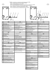
The water pressure in the water supply system should be higher
than 0.1 MPa and lower than 0.5 MPa. If the water pressure is
higher than 0.5 MPa – please refer to the instructions in the section
for connection to the water supply network. Special water heater
models are in production (for regions where local regulations
require) with design to work in plumbing pressure up to 1 MPa.
T
he water containers of the appliances are properly protected
against corrosion by using high quality enameled coating, or are
made of high-range alloy chrome-nickel (corrosion resistant) steel.
Water tanks with enameled coating are equipped with built-in
anodes made of special alloy providing additional protection.
T
he heat isolation is hard (molded) polyurethane
or
expanded
polystyrene
(EPS) with an
outer shell
.
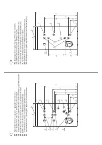
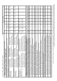
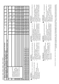
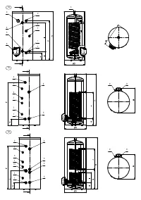
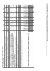
The basic models and modifications are shown on Fig. 1 and 2,
while their specifications are listed in Table 1. Please refer to all
figures and tables in this manual.
T
he water heater models and their modifications are marked with
letters and numbers as follow:
T
he first two letters and following five digits indicate the device
base model.
џ
„
F“ – installation on the floor.
џ
„
V“ – mounting position - vertical .
џ
x
xx - the first three digits after the letter "V", are code of the
water heater tank's capacity range.
џ
y
y - the next two digits are code of the device diameter.
!
L
etter
s
after the base model are:
џ
„
I“ - the water container of the appliance is made of chrome-
nickel steel alloy.
џ
„F
“ -
EPS
insulation
џ
„
S“, „S2“, „S21“,
„S
М“,
„D1
“,
„D2
“ – the water container is
equipped with built-in one or two heat exchangers for water
heating from an alternative heat source (local water heating,
solar collector and any other similar sources). Fig. 1 for "S"
and "S2“, Fig. 2 for „S21“
,
Fig. 1
a
for "S
M
", Fig. 1
b
for "
D1
"
,
Fig. 2
a
for „
D2
“.
џ
„
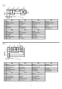
E“ – digital control unit for the heater or for both - the heater
and the devices for heat transfer fluid flow control. These
appliances are accompanied by additional instructions
describing how to use the digital control unit.
!
T
he power for water heaters for ranges up to 200 is up to 3 kW, for
ranges 300-500 - up to 9 kW and up to 12 kW for the rest. Produced
as well are water heaters with heat exchangers which do not have
electric heaters.
!
T
he exact and complete model number, nominal operating
parameters and serial number of purchased water heater are
marked on its plate affixed on its body.
!
I
n order to ease transportation the water heaters are attached to
individual transport pallets.
W
ATER HEATER INSTALLATION ON THE FLOOR
OF THE PREMISE
T
he water heater can be installed only in normal fire safeguarded
premises and where temperature cannot fall under 0 °C. The
availability of a siphon of the installation for waste waters is
necessary on the floor of the premse because during normal
usage of the water heater, water may leak from the combined
valve. At the same time the siphon will facilitate the water tank
maintenance, prevention and servicing operations when water
needs to be drained out of the water tank.
T
he installation location of the water heater must comply with the
outline dimensions, the location of its pipes, and the degree of
protection against water penetration. The latter is marked on the
appliance production plate with its serial number. The appliance
must be protected from water dripping or spraying. The location of
the water heater instalment must be levelled. A distance between
the unit and surrounding walls and ceiling must be allowed in order
to complete the necessary electric and water connections, but not
less than 100 mm.
B
efore the installation of the appliance if it has been supplied with
transport pallet, start with removing the pallet. Water heaters by
ranges up to 500 are equipped with 3 pcs. feets (supports). If the
supports are not in place they have to be screwed in the apertures
which the device was attached to the transport pallet. The screwed
part allows additional appliance levelling. Larger water heaters
must be attached to the room floor through the same openings that
serve for its attachment to the transport pallet.
WARNING!
Non observance of the requirements for fixing the
water heater may cause damages to the appliance, to other
appliances and the premises, where the device is located, as
well as corrosion of the casing or even more serious failures
and damages. In such cases eventual failures and damages
are not a subject to manufacturer and seller warranty liabilities
and will be at the expense of the party which has not observed
the present instructions manual.
T
he removal from the transport pallet and the installation of the
water heater on the room floor must be carried out by qualified
persons who are due to take all necessary precautions to prevent
accidents.
W
ATER HEATER CONNECTION TO THE WATER
SUPPLY NETWORK
T
he water heater connection to the water supply network must be
performed only by a qualified service company.
T
he plumbing (water supply network) to which the water heater will
be connected, as well as any other of its elements shall have to
withstand sustained water temperatures above 80 °C and for short
periods – above 100 °C, as well as to pressure at least twice higher
then the appliance work pressure.
T
he pipes for cold (inlet) and warm (outlet) water of the water
heater are identified by labels with the appropriate inscriptions.
W
here the plumbing pipes are copper or of another metal, other
than that of the water tank, or where brass fasteners are used, it is
obligatory
to install on the water heater inlet and outlet non-metallic
couplings (dielectric fittings).
W
ater heaters by ranges up to 500 are equipped with a combined
valve – safety valve and non-return valve located in a common
body. The combined valve must be fitted onto the inlet pipe of the
tank, in keeping with the arrow on the body showing direction of the
water passing through it.
T
he water heaters by ranges 750 and more are equipped with
EN
16
EN
Содержание
- 45 БЕЗОПАСНОСТЬ, ОСНОВНЫЕ ТРЕБОВАНИЯ; Подключение водонагревателя с встроенными теплообменниками к
- 47 Н е с о б л ю д е н и е т р е б о в а н и й к
- 49 ИСПОЛЬЗОВАНИЕ ВОДОНАГРЕВАТЕЛЯ; АНТИКОРРОЗИЙНАЯ ЗАЩИТА; Водонагреватель с эмалированным баком
- 50 Для обеспечения безопасной и; НЕИСПРАВНОСТИ; Неправильной транспортировкой


