Пилы торцовочные Bosch 0.601.B19.200 - инструкция пользователя по применению, эксплуатации и установке на русском языке. Мы надеемся, она поможет вам решить возникшие у вас вопросы при эксплуатации техники.
Если остались вопросы, задайте их в комментариях после инструкции.
"Загружаем инструкцию", означает, что нужно подождать пока файл загрузится и можно будет его читать онлайн. Некоторые инструкции очень большие и время их появления зависит от вашей скорости интернета.
34
| English
1 609 92A 3UK | (07.08.2018)
Bosch Power Tools
u
Do not stand in line with the saw blade in front of the
power tool. Always stand to the side of the saw blade.
This protects your body against possible kickback.
– Keep hands, fingers and arms away from the rotating saw
blade.
– Do not reach one hand across the other when in front of
the tool arm.
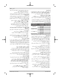
Permissible workpiece dimensions
Maximum
workpiece dimensions:
Mitre angle
Bevel angle
Height x width
[mm]
0°
0°
70 x 312
45° (right/left)
0°
70 x 225
0°
45° (left)
45 x 312
0°
45° (right)
20 x 312
45°
45° (left)
45 x 225
45°
45° (right)
20 x 225
45° (right/left)
45° (left with SDS
bolt)
30 x 225
Minimum workpiece dimensions (= all workpieces that can
be secured left or right of the saw blade using the supplied
screw clamps
(28)
): 100 x 40 mm (length x width)
Max. cutting depth (0°/0°): 70 mm
Replacing the insert plates (see figure O)
The red insert plates
(19)
can become worn after prolonged
use of the power tool.
Replace defective insert plates.
– Bring the power tool into the work position.
– Loosen the screws
(53)
with a hex key (4 mm) and re-
move the old insert plates.
– Insert the new right-hand insert plate.
– Screw the insert plate as far as possible to the right with
the screws
(53)
so that the saw blade does not come into
contact with the insert plate over the entire length of the
possible slide motion.
– Repeat the work steps in the same manner for the left-
hand insert plate.
Sawing
u
Always tighten the locking knob
(21) and the clamp-
ing lever (41) firmly before sawing.
Otherwise the saw
blade can become wedged in the workpiece.
Adjusting the speed
The speed regulator
(38)
enables continuously variable ad-
justment of the speed of the power tool even during opera-
tion.
Note:
Always set the suitable speed for the workpiece ma-
terial (see table below). This will prevent the saw teeth over-
heating when sawing.
Speed setting
Speed
Material
1
3500 rpm
Aluminium
2
3800 rpm
Speed setting
Speed
Material
3
4100 rpm
Plastics
4
4400 rpm
5
4700 rpm
Wood
6
5300 rpm
Sawing without slide movement (cutting off) (see figure
P)
– For cuts without slide movement (small workpieces),
loosen the locking screw
(33)
if it is tightened. Push the
tool arm all the way towards the fence
(14)
and retighten
the locking screw
(33)
.
– Set the required mitre and/or bevel angle as necessary.
– Firmly clamp the workpiece as appropriate for its dimen-
sions.
– Switch the power tool on.
– Slowly guide the tool arm downwards using the handle
(9)
.
– Saw through the workpiece applying uniform feed.
– Switch off the power tool and wait until the saw blade has
come to a complete stop.
– Slowly guide the tool arm upwards.
Sawing with slide movement
– For cuts made using the slide device
(1)
(wide work-
pieces), loosen the locking screw
(33)
if it is tightened.
– Set the required mitre and/or bevel angle as necessary.
– Firmly clamp the workpiece as appropriate for its dimen-
sions.
– Pull the tool arm away from the fence
(14)
until the saw
blade is in front of the workpiece.
– Switch the power tool on.
– Slowly guide the tool arm downwards using the handle
(9)
.
– Now push the tool arm towards the fence
(14)
and saw
through the workpiece with uniform feed.
– Switch off the power tool and wait until the saw blade has
come to a complete stop.
– Slowly guide the tool arm upwards.
Sawing workpieces of the same length (see figure Q)
The length stop
(36)
(accessory) can be used for easily saw-
ing workpieces to the same length.
The length stop can be mounted on either side of the saw
table extension
(13)
.
– Loosen the locking screw
(54)
and move the length stop
(36)
over the clamping screw
(55)
.
– Retighten the locking screw
(54)
.
– Set the saw table extension
(13)
to the required length
(see "Extending the saw table (see figure
Adjusting the depth stop (sawing the groove) (see figure
R)
The depth stop needs to be adjusted if you wish to saw a
groove.
– Swivel the depth stop
(32)
outwards.
Содержание
- 232 Сервис
- 233 Символы; Символы и их значение
- 234 Описание продукта и услуг; Применение по назначению
- 235 Технические данные; Панельная пила
- 236 Данные о шуме; Используйте средства защиты органов слуха!; Сборка; Комплект поставки; Монтаж на верстаке производства Bosch
- 237 Удаление пыли и стружки; Избегайте скопления пыли на рабочем месте.; Замена пильного диска; Монтаж с помощью винта с внутренним
- 238 Работа с инструментом; Подготовка эксплуатации; Смещение упорной планки
- 239 Настройка горизонтального угла распила; слева; Настройка вертикального угла распила
- 240 Включение электроинструмента
- 241 Пиление; Установка числа оборотов; Основные настройки – контроль и коррекция
- 243 Техобслуживание и сервис; Техобслуживание и очистка; мер
- 244 Утилизация; Українська; Вказівки з техніки безпеки; ДЖЕННЯ
Характеристики
Остались вопросы?Не нашли свой ответ в руководстве или возникли другие проблемы? Задайте свой вопрос в форме ниже с подробным описанием вашей ситуации, чтобы другие люди и специалисты смогли дать на него ответ. Если вы знаете как решить проблему другого человека, пожалуйста, подскажите ему :)


