
Гайковерты Bosch 1/2″ 310Нм - инструкция пользователя по применению, эксплуатации и установке на русском языке. Мы надеемся, она поможет вам решить возникшие у вас вопросы при эксплуатации техники.
Если остались вопросы, задайте их в комментариях после инструкции.
"Загружаем инструкцию", означает, что нужно подождать пока файл загрузится и можно будет его читать онлайн. Некоторые инструкции очень большие и время их появления зависит от вашей скорости интернета.


English |
19
Bosch Power Tools
3 609 929 C65 | (5.8.13)
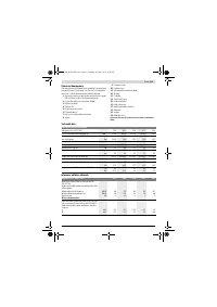
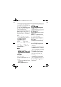
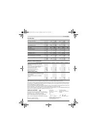
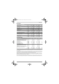
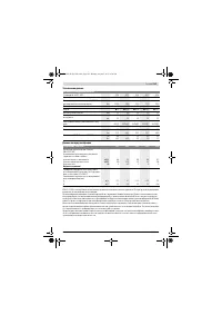
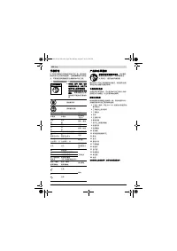
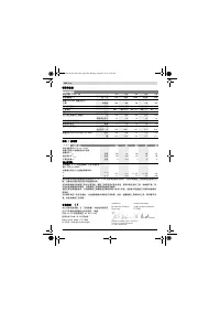
Declaration of Conformity
We declare under our sole responsibility that the product de-
scribed under “Technical Data” is in conformity with the fol-
lowing standards or standardization documents:
EN ISO 11148 according to the provisions of the directive
2006/42/EC.
Technical file (2006/42/EC) at:
Robert Bosch GmbH, PT/ETM9
D-70745 Leinfelden-Echterdingen
Robert Bosch GmbH, Power Tools Division
D-70745 Leinfelden-Echterdingen
Leinfelden, 08.08.2013
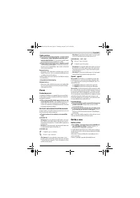
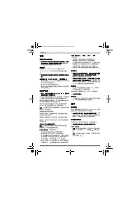
Assembly
Devices for Safe Handling
If you want to operate the pneumatic tool in a suspen-
sion device or a clamping fixture, take care to fasten it
in the device/fixture first before connecting it to the air
supply.
This measure prevents accidental starting of oper-
ation.
Suspension Device
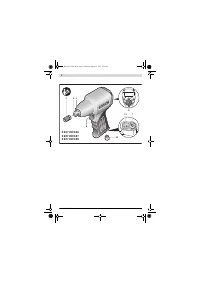
You can fasten the pneumatic tool to a suspension device us-
ing the suspension hook
4
(0 607 450 593) or the utility clip
14
(0 607 450 622).
Regularly check the condition of the suspension hook
or the utility clip and the hook in the suspension device.
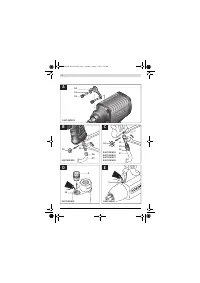
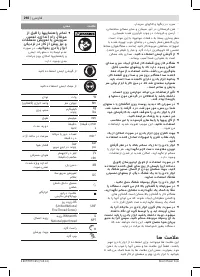
Fastening the Utility Clip (0 607 450 622) (see figure A)
– Screw the upper, front screws
12
with an Allen key (6 mm)
in an anticlockwise direction from the housing of the pneu-
matic tool.
– Remove the washers
13
and place them onto the screws
12
.
– Firmly screw the utility clip
14
with the screws and wash-
ers in a clockwise direction on the housing of the pneumat-
ic tool.
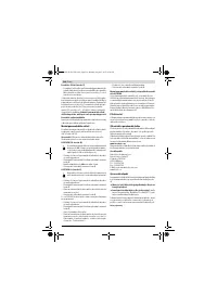
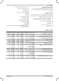
Connecting the Air Supply
Pay attention that the air pressure is not less than
6.3 bar (91 psi), as the pneumatic tool is designed for
this operating pressure.
For maximum performance, the values for the inner hose di-
ameter as well as the connection threads must be adhered to
as listed in the “Technical Data” Table. To maintain the full
performance, only use hoses with a maximum length of 4 m.
The compressed air supplied should be free of foreign materi-
al and moisture to protect the tool from damage, contamina-
tion, and the formation of rust.
Note:
The use of a compressed-air maintenance unit is neces-
sary. This ensures proper function of the pneumatic tools.
Observe the operating instructions of the maintenance unit.
All fittings, connecting lines and hoses must be dimensioned
for the pressure and the required air volume.
Avoid restrictions in the air supply, e. g., from pinching, kink-
ing, or stretching!
When in doubt, check the pressure at the air inlet with a pres-
sure gauge with the pneumatic tool switched on.
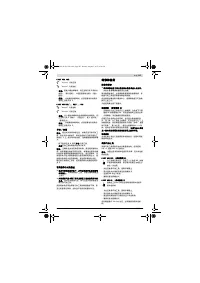
Connecting the Air Supply to the Pneumatic Tool
Note:
Always mount the supply-air hose to the pneumatic tool
first, then to the maintenance unit.
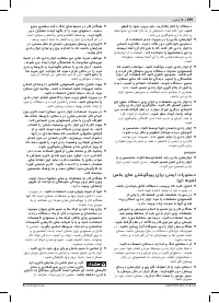
0 607 450 593
(see figure B)
– Remove the closing cap
10
from the connection thread at
the air inlet
7
.
– Screw a hose fitting
15
into the connection thread at the
air inlet
7
.
To avoid damage to interior valve components of the pneu-
matic tool when screwing the hose fitting
15
in or out, it is
recommended to counter-hold the projecting connection
thread at the air inlet
7
with an open-end wrench (size
26 mm).
– Loosen hose clamp
16
of supply-air hose
17
, mount the
supply-air hose to hose fitting
15
and retighten the hose
clamp.
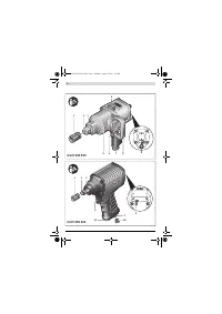
0 607 450 622/... 626/... 627/... 628
(see figure C)
– Remove the closing cap
10
from the connection thread at
the air inlet
7
.
– Screw a tube connector
18
into the connection thread at
air inlet
7
.
To avoid damage to interior valve components of the pneu-
matic tool when screwing the tube connector
18
in or out,
it is recommended to counter-hold the projecting connec-
tion thread at air inlet
7
with an open-end wrench (size
22 mm).
– Place the supply-air hose
17
with the appropriate clutch
19
onto the tube connector
18
.
Changing the Tool
Disconnect the air supply before making any adjust-
ments, changing accessories, or placing the pneumatic
tool aside.
This safety measure prevents accidental start-
ing of the pneumatic tool.
When working with an application tool, pay attention
that the application tool is firmly seated on the tool
holder.
When the application tool is not firmly connected
with the tool holder, it can come loose again and not be
controlled.
Inserting
– Slide the application tool
1
over the square drive of the tool
holder
3
. Pay attention that the snap ring
2
locks in the
groove of the application tool.
Use only application tools with an appropriate shank end (see
“Technical Data”).
Do not use adapters.
Removing
– Pull off the application tool
1
from the tool holder
3
. A
seized application tool can be loosened by applying light
blows with a rubber hammer.
Henk Becker
Executive Vice President
Engineering
Helmut Heinzelmann
Head of Product Certification
PT/ETM9
OBJ_DOKU-37022-001.fm Page 19 Monday, August 5, 2013 5:05 PM
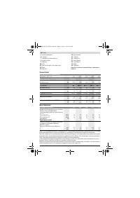
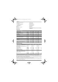
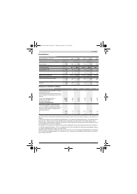
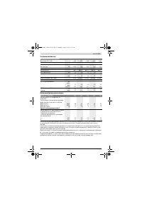
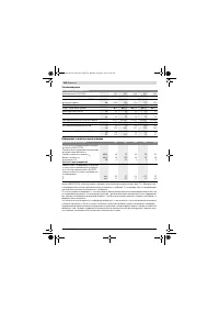
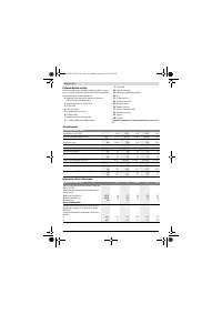
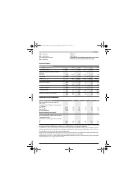
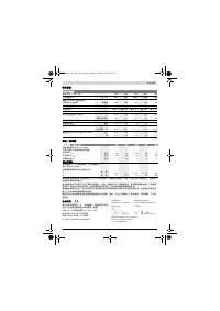
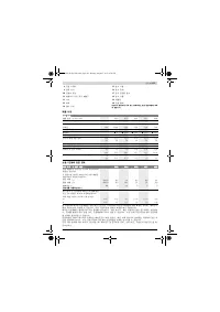
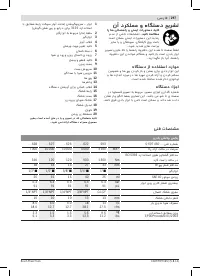
Характеристики

Остались вопросы?Не нашли свой ответ в руководстве или возникли другие проблемы? Задайте свой вопрос в форме ниже с подробным описанием вашей ситуации, чтобы другие люди и специалисты смогли дать на него ответ. Если вы знаете как решить проблему другого человека, пожалуйста, подскажите ему :)


