Электропилы Bosch GTS 10 XC - инструкция пользователя по применению, эксплуатации и установке на русском языке. Мы надеемся, она поможет вам решить возникшие у вас вопросы при эксплуатации техники.
Если остались вопросы, задайте их в комментариях после инструкции.
"Загружаем инструкцию", означает, что нужно подождать пока файл загрузится и можно будет его читать онлайн. Некоторые инструкции очень большие и время их появления зависит от вашей скорости интернета.


English |
39
Bosch Power Tools
1 619 929 K16 | (29.8.11)
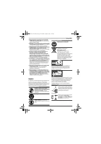
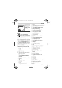
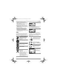
– Turn the saw blade until the marked tooth projects above
the right side of the insert plate.
– Move the angle gauge alongside the guide groove to the
marked tooth.
– Measure the clearance between the saw blade and guide
groove again.
Both clearances measured must be identical.
Adjusting:
– Loosen Allen screws
70
at the front below the saw table
and Allen screws
71
at the rear below the saw table with
the supplied Allen key
37
.
– Carefully move the saw blade until it is parallel to guide
groove
9
.
– Retighten all screws
70
and
71
again.
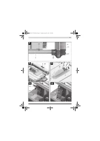
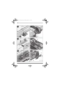
Adjusting the Saw Table’s Clearance Indicator
(see figure O)
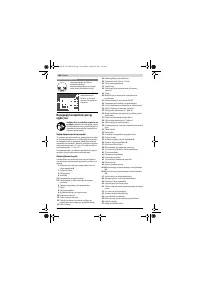
– Position the parallel guide on the right side of the saw
blade.
Move the parallel guide until the mark in the lens
64
indi-
cates 33 cm on the bottom scale.
To lock the parallel guide, press clamping handle
47
down
again.
– Completely pull clamping handle
18
upward and pull the
table width enlargement
11
outward to the stop.
Checking:
On the upper scale
1
, clearance indicator
65
must indicate
the identical value as the mark in lens
64
on the bottom scale
1
.
Adjusting:
– Loosen screw
72
with a Phillips screwdriver and align
clearance indicator
65
alongside the 33 cm mark of the up-
per scale
1
.
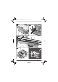
Adjusting the Lens of the Parallel Guide (see figure P)
– Bring the power tool into the working position.
– Tilt the blade guard
5.x
toward the rear to the stop.
– Move parallel guide
8
from the right until it touches the saw
blade.
Checking:
The mark of lens
64
must be in a line with the 0 ° mark of scale
1
.
Adjusting:
– Loosen screw
73
using a Phillips screwdriver and align the
clearance indicator alongside the 0 ° mark.
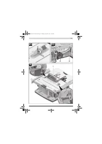
Adjusting the Level of the Insert Plate (see figure Q)
Checking:
The front side of the insert plate
31
must be flush with or
somewhat lower than the saw table; the rear side must be
flush with or somewhat above the saw table.
Adjusting:
– Adjust the correct level of the four adjusting screws
74
with a suitable slotted screwdriver.
Adjusting the Tension Force of the Parallel Guide
The tensioning force of the parallel guide
8
can decrease after
frequent usage.
– Tighten the adjustment screw
81
until the parallel guide
can be firmly affixed on the saw table again.
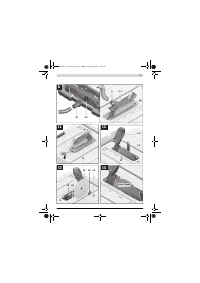
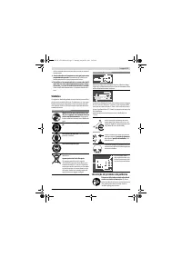
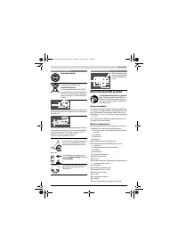
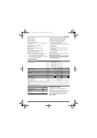
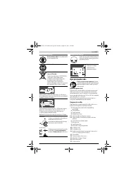
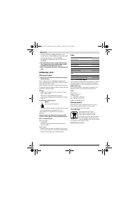
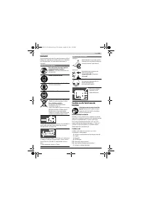
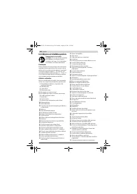
Storage and Transport
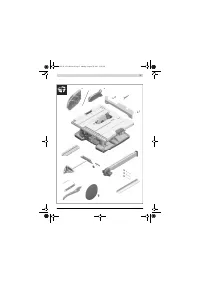
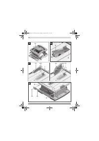
Storing Product Features (see figures R1 – R6)
For storage purposes, certain product features can be se-
curely fastened to the power tool.
– Loosen auxiliary parallel guide
49
from parallel guide
8
.
– Attach all loose tool parts to their storage locations on the
housing. (see Table)
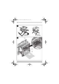
Carrying the Power Tool
Before transporting the power tool, the following steps must
be carried out:
– Bring the machine into the transport position.
(see “Transport Position”, page 36)
– Remove all accessories that cannot be mounted firmly to
the power tool.
If possible, place unused saw blades in an enclosed con-
tainer for transport.
– Slide the table width enlargement
11
completely in and
press tensioning lever
18
downward to lock it.
– Slide the table extension
10
completely in and firmly tight-
en the locking screws
38
on the guide rods
24
.
– Wind the mains cable around the cable holder
42
.
– For lifting or transport, use the carrying handles
4
.
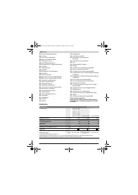
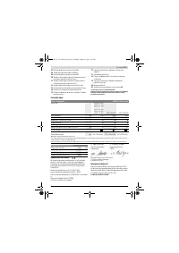
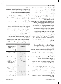
Figure Product Feature Storage Location
R1
Blade guard
5.x
Insert into the recess of fixture
22
and tighten with clamping
lever
46.1
or clamping screw
46.2
R2
“Auxiliary parallel
guide” fastening
kit
39
Clip into the holders
75
R2
Extraction
adapter
41
Insert into retaining clamp
76
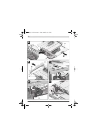
R3
Unused saw
blades
Insert into saw blade storage
77
and lock the cover
14
over it
with fastening nut
12
R3
Ring spanner
15
Insert into saw blade storage
77
and lock the cover
14
over it
with fastening nut
12
R3
Push stick
13
Lock in place with fastening nut
12
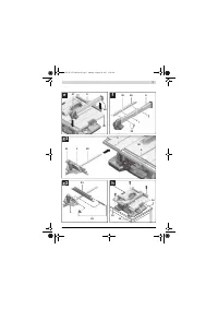
R4
Allen key
37
Insert into holders
78
R4
Parallel guide
8
Insert into the storage compart-
ment for the parallel guide
36
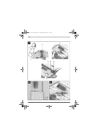
R5
Angle stop
3
Insert into retaining clamp
23
R6
Auxiliary parallel
guide
49
Insert into the storage compart-
ment for the auxiliary parallel
guide and lock in place with the
retaining bracket
79
OBJ_BUCH-1375-002.book Page 39 Monday, August 29, 2011 5:05 PM


