Электропилы Bosch GTS 10 XC - инструкция пользователя по применению, эксплуатации и установке на русском языке. Мы надеемся, она поможет вам решить возникшие у вас вопросы при эксплуатации техники.
Если остались вопросы, задайте их в комментариях после инструкции.
"Загружаем инструкцию", означает, что нужно подождать пока файл загрузится и можно будет его читать онлайн. Некоторые инструкции очень большие и время их появления зависит от вашей скорости интернета.


34
| English
1 619 929 K16 | (29.8.11)
Bosch Power Tools
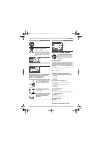
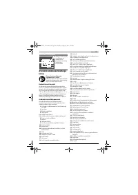
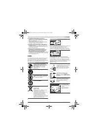
Note:
Check the power tool for possible damage.
Before further use of the machine, check that all protective
devices are fully functional. Any lightly damaged parts must
be carefully checked to ensure flawless operation of the tool.
All parts must be properly mounted and all conditions fulfilled
that ensure faultless operation.
Damaged protective devices and parts must be immediately
replaced by an authorised service centre.
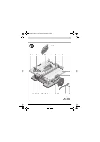
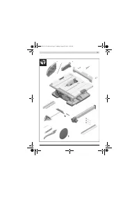
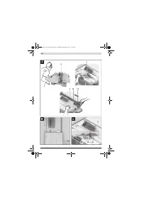
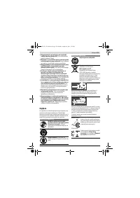
Mounting Individual Components
– Carefully remove all parts included in the delivery from
their packaging.
– Remove all packaging material from the machine and the
accessories provided.
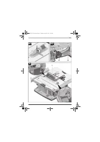
– Open the bottom plate
44
and remove the packaging ma-
terial under the motor block. (see figure a)
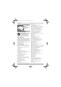
The following product features are fastened directly to the
housing:
Push stick
13
, ring spanner
15
, Allen key
37
, parallel guide
8
,
angle guide
3
, extraction adapter
41
, auxiliary parallel guide
49
with fastening kit
39
, blade guard
5.x
.
– Carefully remove these product features from their stor-
age locations.
Also see figures R1 – R6.
Additionally required tools (not in delivery scope):
– Slotted screwdriver
– Phillips screwdriver
– Angle gauge
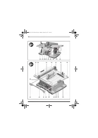
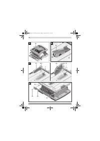
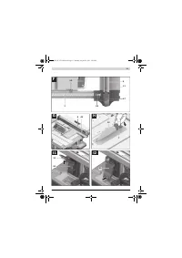
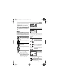
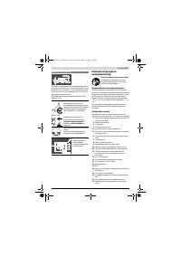
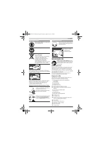
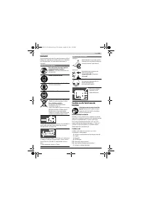
Mounting the Insert Plate(see figure b)
– Hook insert plate
31
into the rear insert-plate notches
45
of the tool basin.
– Guide the insert plate down.
– Press on the insert plate until it engages at the front in the
tool basin.
The front side of the insert plate
31
must be flush with or
somewhat lower than the saw table; the rear side must be
flush with or somewhat above the saw table. (also see “Ad-
justing the Level of the Insert Plate”, page 39)
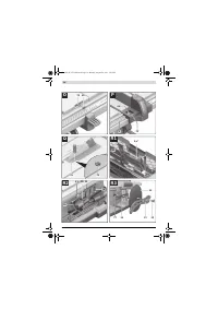
Mounting the Blade Guard* (see figure c)
* depending on country version
– Turn crank
20
clockwise to the stop, so that the saw blade
32
is in the highest possible position above the saw table.
– Insert the blade guard
5.x
into the recess in riving knife
7
.
– Tighten the clamping lever
46.1
.
or
Tighten clamping screw
46.2
with Allen key
37
.
– Adjust the blade guard according to the workpiece height.
When sawing, the blade guard must always face lightly
against the workpiece.
Note:
Clamping lever
46.1
is indexed (adjustable), allowing it
to be set to an ergonomically favourable or space-saving posi-
tion.
With the clamping lever tightened, pull its lever away from the
blade guard, turn it to the desired position and allow it to en-
gage again.
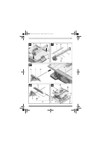
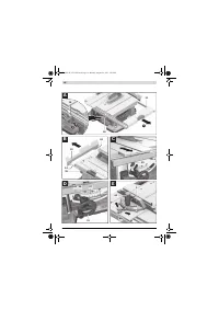
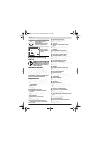
Mounting the Table Extension (see figure d)
For assembly, use the fastening kit for “table extension”
43
.
(2 fastening screws, 2 washers, 1 open-end spanner)
– Bolt the table extension
10
with the guide rods
24
.
When doing this, the recesses in the table extension must
face upward.
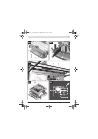
Mounting the Parallel Guide (see figure e)
The parallel guide
8
can be positioned either left or right from
the saw blade.
– Loosen clamping handle
47
of parallel guide
8
.
This releases V-guide
48
.
– Firstly, mount the parallel guide via the V-guide in guide
groove
30
of the saw table. Now, position the parallel
guide into the front guide groove
35
of the saw table.
The parallel guide can now be moved to any position.
– To lock the parallel guide, press the clamping handle
47
down.
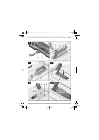
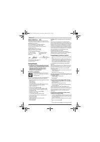
Mounting the Auxiliary Parallel Guide (see figure f)
When sawing narrow workpieces and bevel angles,
the
auxiliary parallel guide
49
must be mounted to parallel guide
8
.
The auxiliary parallel guide can be mounted left or right from
parallel guide
8
, as required.
For assembly, use the “auxiliary parallel guide” fastening kit
39
. (3 fastening screws, 3 washers, 3 wing nuts)
– Insert the fastening screws through the lateral holes in the
parallel guide
8
.
The heads of the screws serve as a guide for the auxiliary
parallel guide.
– Move the auxiliary parallel guide
49
over the heads of the
fastening screws.
– Mount the washers to the fastening screws and tighten
them with the wing nuts .
Mounting the Angle Stop (see figures g1 – g2)
– Insert the guide rail
50
of the angle stop
3
into one of the
guide grooves
9
of the saw table intended for this purpose.
Note:
In the lefthand guide groove, the position of the angle
stop can be affixed on the sliding table by tightening the
knurled screw
51
.
For improved placement of long workpieces, the angle stop
can be extended with profile rail
34
.
– If required, mount the profile rail to the angle stop with fas-
tening kit
52
.
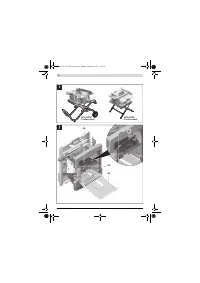
Stationary or Flexible Mounting
f
To ensure safe handling, the machine must be mounted
on a level and stable surface (e. g., workbench) prior to
using.
Mounting to a Working Surface (see figure h)
– Fasten the power tool with suitable screw fasteners to the
working surface. The mounting holes
16
serve for this pur-
pose.
OBJ_BUCH-1375-002.book Page 34 Monday, August 29, 2011 5:05 PM


