Электропилы Bosch GTS 10 XC - инструкция пользователя по применению, эксплуатации и установке на русском языке. Мы надеемся, она поможет вам решить возникшие у вас вопросы при эксплуатации техники.
Если остались вопросы, задайте их в комментариях после инструкции.
"Загружаем инструкцию", означает, что нужно подождать пока файл загрузится и можно будет его читать онлайн. Некоторые инструкции очень большие и время их появления зависит от вашей скорости интернета.


38
| English
1 619 929 K16 | (29.8.11)
Bosch Power Tools
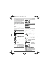
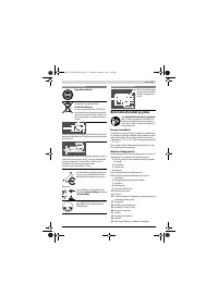
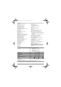
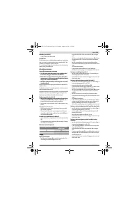
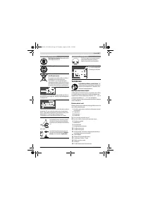
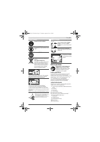
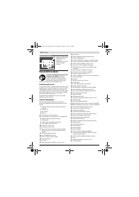
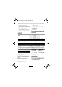
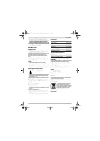
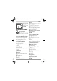
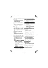
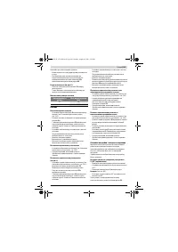
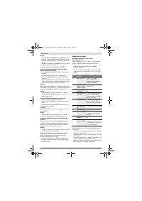
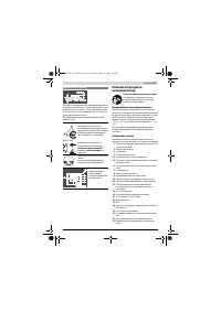
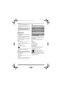
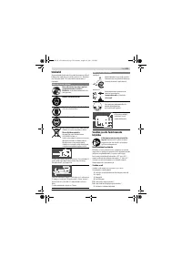
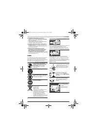
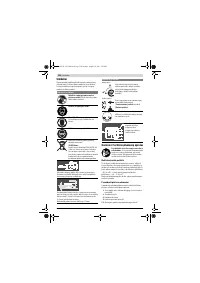
Maximum Workpiece Dimensions
Sawing
Sawing Straight Cuts
– Adjust the parallel guide
8
to the requested cutting width.
(see “Adjusting the Parallel Guide”, page 36)
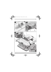
– Position the workpiece on the saw table in front of the
blade guard
5.x
.
– Raise or lower the saw blade with the crank
20
so that the
upper saw teeth project approx. 5 mm above the work-
piece surface.
– Adjust the blade guard according to the workpiece height.
When sawing, the blade guard must always face lightly
against the workpiece.
– Switch on the machine.
– Saw through the workpiece applying uniform feed.
– Switch off the machine and wait until the saw blade has
come to a complete stop.
Sawing Bevel Angles
– Adjust the desired bevel angle. (see “Adjusting Bevel An-
gles”, page 36)
– Follow the worksteps in section “Sawing Straight Cuts” ac-
cordingly.
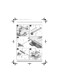
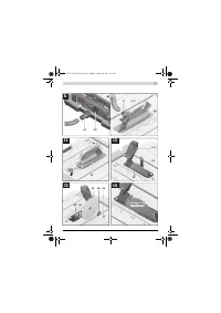
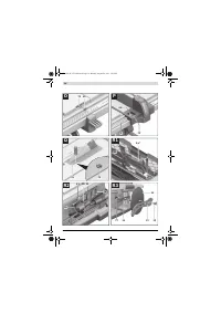
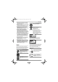
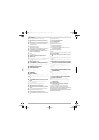
Sawing Mitre Angles (see figure L)
– Adjust the requested mitre angle (see “Adjusting Mitre An-
gles”, page 36)
– Place the workpiece against profile rail
34
.
The profile may not be on the cutting line. If so, loosen
knurled nut
53
and move the profile.
– Raise or lower the saw blade with the crank
20
so that the
upper saw teeth project approx. 5 mm above the work-
piece surface.
– Adjust the blade guard according to the workpiece height.
When sawing, the blade guard must always face lightly
against the workpiece.
– Switch on the machine.
– With one hand, press the workpiece against the profile rail
and with the other hand, slowly move the angle stop via
locking knob
62
toward the front in guide groove
9
.
– Switch off the machine and wait until the saw blade has
come to a complete stop.
Sawing Mitre Angles with the Sliding Table Locked
– Adjust the requested mitre angle (see “Adjusting Mitre An-
gles”, page 36)
– The angle stop must move freely in the guide groove
9
(left-
ward or rightward).
For this, loosen knurled screw
51
, if required.
– Follow the worksteps in section “Sawing Straight Cuts” ac-
cordingly.
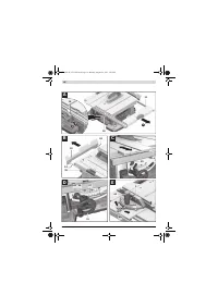
Sawing Mitre Angles with the Sliding Table
– Adjust the requested mitre angle (see “Adjusting Mitre An-
gles”, page 36)
– Completely pull clamping handle
29
for the sliding table
upward and pull the sliding table
2
toward the front.
– Position the workpiece on the saw table in front of the
blade guard
5.x
.
– Position the angle stop
3
in front of the workpiece in the
lefthand guide groove
9
. Lock this position by firmly tight-
ening the knurled screw
51
.
– Follow the worksteps in section “Sawing Straight Cuts” ac-
cordingly.
Checking and Adjusting the Basic Adjustment
To ensure precise cuts, the basic adjustment of the machine
must be checked and adjusted as necessary after intensive
use.
A certain level of experience and appropriate specialty tools
are required for this.
A Bosch after-sales service station will handle this mainte-
nance task quickly and reliably.
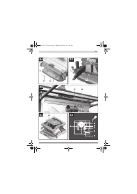
Setting the Stops for Standard 0 ° / 45 ° Bevel Angles
– Bring the power tool into the working position.
– Adjust to a 0 ° bevel angle.
– Tilt the blade guard
5.x
toward the rear to the stop.
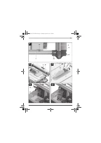
Checking:
(see figure M1)
– Set an angle gauge to 90 ° and place it on the saw table
17
.
The leg of the angle gauge must be flush with the saw blade
32
over the complete length.
Adjusting:
(see figure M2)
– Loosen screw
67
.
The 0 ° stop
28
can now be moved.
– Loosen locking lever
26
.
– Move handwheel
19
toward the 0° stop until the leg of the
angle gauge is flush with the saw blade over the complete
length.
– Hold the handwheel in this position and tighten locking le-
ver
26
again.
– Tighten screw
67
again.
When the angle indicator
61
is not in line with the 0 ° mark of
scale
27
, loosen screw
68
with a commercially available Phil-
lips screwdriver and align the angle indicator alongside the 0 °
mark.
Repeat the above mentioned worksteps accordingly for the
45 ° bevel angle (loosening screw
69
; moving the 45° stop
25
). In this, the angle indicator
61
must not be misadjusted.
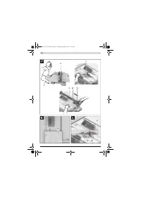
Parallelism of the Saw Blade to the Guide Grooves of the
Angle Stop (see figure N)
– Bring the power tool into the working position.
– Tilt the blade guard
5.x
toward the rear to the stop.
Checking:
– With a pencil, mark the first visible saw tooth on the left
side that projects above the insert plate.
– Set an angle gauge to 90 ° and place it on the edge of the
guide groove
9
.
– Move the leg of the angle gauge until it touches the marked
saw tooth, and read the clearance between saw blade and
guide groove.
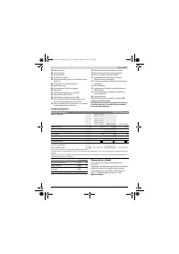
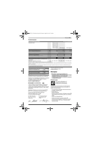
Bevel angle
Max. workpiece height
[mm]
0 °
79
45 °
56
OBJ_BUCH-1375-002.book Page 38 Monday, August 29, 2011 5:05 PM


