Электропилы Bosch GTS 10 XC - инструкция пользователя по применению, эксплуатации и установке на русском языке. Мы надеемся, она поможет вам решить возникшие у вас вопросы при эксплуатации техники.
Если остались вопросы, задайте их в комментариях после инструкции.
"Загружаем инструкцию", означает, что нужно подождать пока файл загрузится и можно будет его читать онлайн. Некоторые инструкции очень большие и время их появления зависит от вашей скорости интернета.


36
| English
1 619 929 K16 | (29.8.11)
Bosch Power Tools
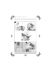
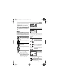
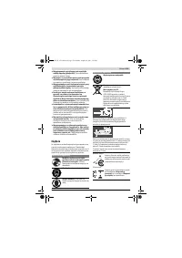
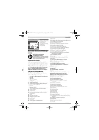
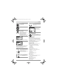
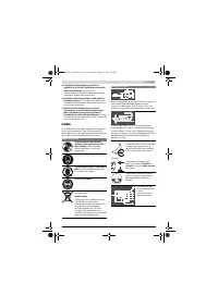
Operation
f
Before any work on the machine itself, pull the mains
plug.
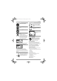
Transport and Working Position of the Saw Blade
Transport Position
– Turn the handwheel
19
in anticlockwise direction until the
teeth of the saw blade
32
are positioned below the saw ta-
ble
17
.
For additional information on transport, see page 39.
Working Position
– Turn the crank
20
clockwise, until the teeth of the saw
blade
32
are positioned above the workpiece.
Note:
Take care that the blade guard is properly positioned.
When sawing, it must always face against the workpiece.
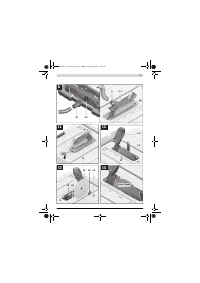
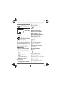
Increasing the Size of the Saw Table
Long workpieces must be underlaid or supported at their free
end.
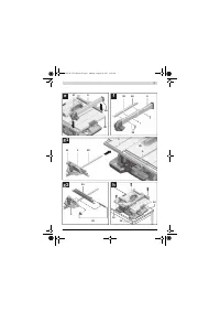
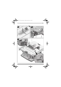
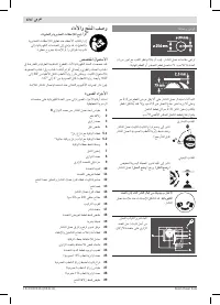
Table Width Enlargement (see figure A)
The table width enlargement
11
enlarges the saw table
17
to-
ward the right by 435 mm (max.).
– Completely pull the clamping handle
18
for the table width
enlargement upward.
– Pull out the table width enlargement
11
to the desired
length (also see “Adjusting the Parallel Guide With the Saw
Table Extended”, page 36).
– Press clamping handle
18
downward.
The table width enlargement is now locked.
Table Extension (see figure B)
The table extension
10
extends saw table
17
to the rear by
520 mm (max.).
– Loosen the locking screws
38
on the guide rods
24
.
– Pull out the table extension
10
to the desired length.
– To lock the position, firmly tighten both locking screws
38
.
For heavy workpieces, it may be required to support the table
extension.
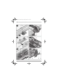
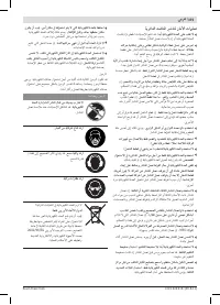
Sliding Table (see figure C)
With the sliding table
2
, workpieces to a maximum width of
350 mm can be sawn.
At the same time, a higher precision is achieved during saw-
ing, especially in conjunction with the angle stop
3
. (see
“Sawing Mitre Angles with the Sliding Table”, page 38)
– Completely pull the clamping lever
29
for the sliding table
upward.
In this manner, the sliding table can be moved both toward
the front as well as toward the rear to the stop.
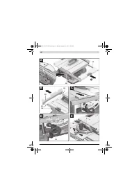
Adjusting the Cutting Angle
To ensure precise cuts, the basic adjustment of the machine
must be checked and adjusted as necessary after intensive
use (see “Checking and Adjusting the Basic Adjustment”,
page 38).
Adjusting Bevel Angles (Saw Blade) (see figure D)
The bevel angle can be set in a range from – 1 ° to +47 ° .
– Turn locking lever
26
in anticlockwise direction.
Note:
By completely loosening the locking knob, the saw
blade tilts approx. to the 30 ° position by means of gravity
force.
– Push or pull handwheel
19
alongside the connecting link
until the angle indicator
61
indicates the desired bevel an-
gle.
– Hold the handwheel in this position and tighten locking le-
ver
26
again.
For quick and precise setting of the standard 0 ° and 45 °
angles, factory-set stops have been provided for.
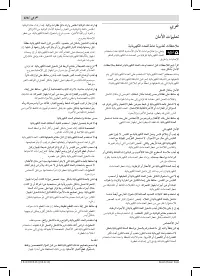
Adjusting Mitre Angles (Angle Stop) (see figure E)
The mitre angle can be set in the range from 60 ° (left side) to
60 ° (right side).
– Loosen the locking knob
62
in case it is tightened.
– Turn the angle stop until the angle indicator
63
indicates
the requested mitre angle.
– Tighten the locking knob
62
again.
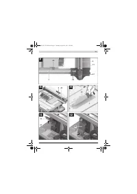
For quick and precise setting of frequently used mitre an-
gles
, stop screw for the 45 ° angles (left and right) and 0 °
have been provided for on angle stop
3
.
– Loosen the locking knob
62
in case it is tightened.
– Tilt the adjustment piece
80
outward.
– Turn the angle stop in such a manner that the thread of the
desired stop screw is positioned rightward to the adjust-
ment piece.
– Tilt adjustment piece
80
inward and turn the angle stop un-
til the thread of the stop screw faces against the adjust-
ment piece.
– Tighten the locking knob
62
again.
Adjusting the Parallel Guide
The parallel guide
8
can be positioned either left (black scale)
or right (silver scale) from the saw blade.
The mark in the lens
64
indicates the set clearance of the par-
allel guide to the saw blade on the scale
1
.
Position the parallel guide on the desired side of the saw
blade (see “Mounting the Parallel Guide”, page 34).
With the Saw Table not Extended
– Loosen clamping handle
47
of parallel guide
8
.
Move the parallel guide until the mark in the lens
64
indi-
cates the desired clearance to the saw blade.
When the saw table is not extended, the bottom labelling of
the silver scale applies
1
.
– To lock the parallel guide, press clamping handle
47
down
again.
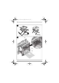
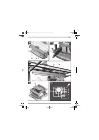
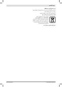
With the Saw Table Extended (see figure F)
– Position the parallel guide on the right side of the saw
blade.
Move the parallel guide until the mark in the lens
64
indi-
cates 33 cm on the bottom scale.
To lock the parallel guide, press clamping handle
47
down
again.
OBJ_BUCH-1375-002.book Page 36 Monday, August 29, 2011 5:05 PM


