Электропилы Bosch GTS 10 XC - инструкция пользователя по применению, эксплуатации и установке на русском языке. Мы надеемся, она поможет вам решить возникшие у вас вопросы при эксплуатации техники.
Если остались вопросы, задайте их в комментариях после инструкции.
"Загружаем инструкцию", означает, что нужно подождать пока файл загрузится и можно будет его читать онлайн. Некоторые инструкции очень большие и время их появления зависит от вашей скорости интернета.


English |
35
Bosch Power Tools
1 619 929 K16 | (29.8.11)
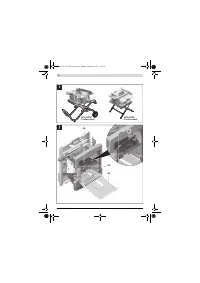
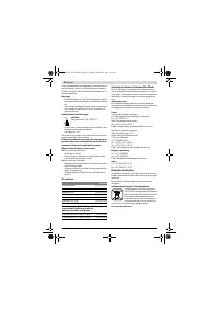
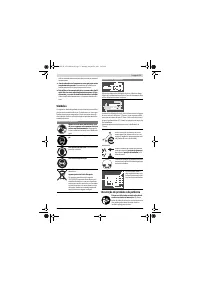
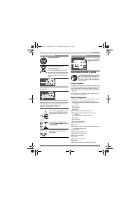
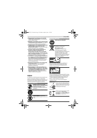
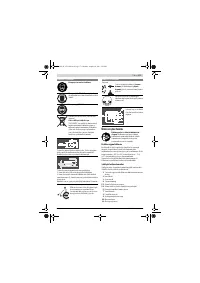
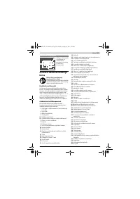
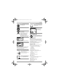
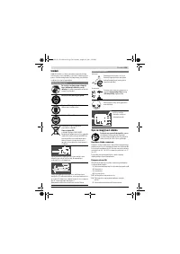
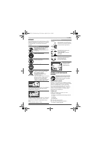
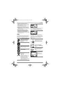
Mounting to a Bosch Saw Stand (see figure i)
With the height-adjustable legs, Bosch saw stands (e. g.
GTA 60 W, GTA 6000) provide firm support for the power
tool on any surface.
f
Read all safety warnings and instructions included with
the worktable.
Failure of observing safety warnings and
instructions can lead to electrical shock, fire and/or cause
serious injuries.
f
Assemble the worktable properly before mounting the
power tool.
Perfect assembly is important in order to pre-
vent the risk of collapsing.
– Mount the power tool in transport position on the saw
stand.
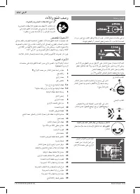
Dust/Chip Extraction
Dusts from materials such as lead-containing coatings, some
wood types, minerals and metal can be harmful to one’s
health. Touching or breathing-in the dusts can cause allergic
reactions and/or lead to respiratory infections of the user or
bystanders.
Certain dusts, such as oak or beech dust, are considered as
carcinogenic, especially in connection with wood-treatment
additives (chromate, wood preservative). Materials contain-
ing asbestos may only be worked by specialists.
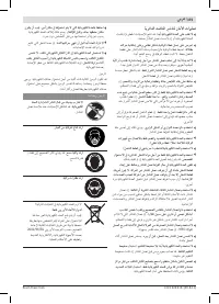
– Always use dust extraction.
– Provide for good ventilation of the working place.
– It is recommended to wear a P2 filter-class respirator.
Observe the relevant regulations in your country for the mate-
rials to be worked.
The dust/chip extraction can be blocked by dust, chips or
workpiece fragments.
– Switch the machine off and pull the mains plug from the
socket outlet.
– Wait until the saw blade has come to a complete stop.
– Determine the cause of the blockage and correct it.
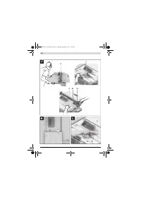
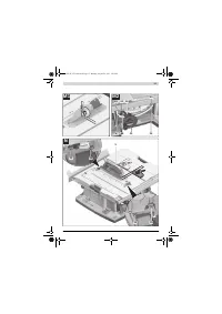
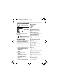
Cleaning the Lower Saw Blade Cover (see figure j)
The lower saw blade cover
54
can be opened for removal of
workpiece fragments and large chips.
– Switch the machine off and pull the mains plug from the
socket outlet.
– Wait until the saw blade has come to a complete stop.
– Tilt the machine on it’s side.
– Remove bottom plate
44
.
– Loosen fastening screw
55
and open the lower saw blade
cover
54
.
– Remove workpiece fragments and chippings.
– Shut the lower saw blade cover and screw it on again.
Screw the bottom plate on again.
– Bring the power tool into the working position.
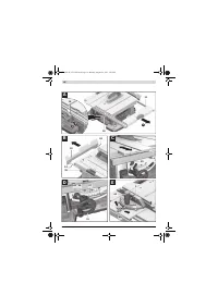
External Dust Extraction (see figure k)
To connect a vacuum cleaner to the sawdust ejector
40
, use
the supplied extraction adapter
41
.
– Firmly attach the extraction adapter
41
and the vacuum
hose.
– Additionally, a dust extraction system can be connected
with the Y-adapter (accessory) to vacuum connection
6
, to
increase the extraction performance.
The vacuum cleaner must be suitable for the material being
worked.
When vacuuming dry dust that is especially detrimental to
health or carcinogenic, use a special vacuum cleaner.
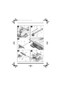
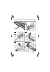
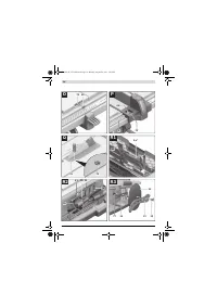
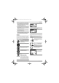
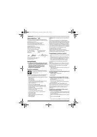
Changing the Saw Blade (see figures l1
–
l4)
f
Before any work on the machine itself, pull the mains
plug.
f
When mounting the saw blade, wear protective gloves.
Danger of injury when touching the saw blade.
Use only saw blades whose maximum permitted speed is
higher than the no-load speed of the power tool.
Use only saw blades that correspond with the characteristic
data given in these operation instructions and that are tested
and marked in accordance with EN 847-1.
Use only saw blades recommended by the tool manufacturer,
and suitable for sawing the materials to be cut.
Removing the Saw Blade
– Using a screwdriver, raise the insert plate
31
at the front
and remove it from the tool basin.
– Turn crank
20
clockwise to the stop, so that the saw blade
32
is in the highest possible position above the saw table.
– Tilt the blade guard
5.x
toward the rear to the stop.
– Turn the clamping nut
56
with the ring spanner
15
(24 mm) and at the same time, pull the spindle lock lever
57
until it engages.
– Keep the spindle lock lever pulled and unscrew the clamp-
ing nut turning in anticlockwise direction.
– Remove the clamping flange
58
.
– Remove the saw blade
32
.
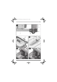
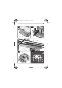
Mounting the Saw Blade
If required, clean all parts to be mounted prior to assembly.
– Place the new saw blade onto the supporting flange
59
of
the tool spindle
60
.
Note:
Do not use saw blades that are too small. The clearance
between saw blade and riving knife must not exceed 5 mm
(max.).
f
When mounting the saw blade, pay attention that the
cutting direction of the teeth (arrow direction on the
saw blade) corresponds with the direction of the arrow
on the blade guard!
– Mount the clamping flange
58
and the clamping nut
56
.
– Turn the clamping nut
56
with the ring spanner
15
(24 mm) and at the same time, pull the spindle lock lever
57
until it engages.
– Tighten the clamping nut in clockwise direction.
(Tightening torque approx. 15 – 23 Nm)
– Reinsert the insert plate
31
.
– Tilt blade guard
5.x
down again.
OBJ_BUCH-1375-002.book Page 35 Monday, August 29, 2011 5:05 PM


