
Водонагреватели ELDOM Green Line WV12046SRD - инструкция пользователя по применению, эксплуатации и установке на русском языке. Мы надеемся, она поможет вам решить возникшие у вас вопросы при эксплуатации техники.
Если остались вопросы, задайте их в комментариях после инструкции.
"Загружаем инструкцию", означает, что нужно подождать пока файл загрузится и можно будет его читать онлайн. Некоторые инструкции очень большие и время их появления зависит от вашей скорости интернета.


The type and nature of wall construction material, the appliance dimensions,
the way of fixing it, the location of its fixing elements and tubes, its protection
against dripping water must be taken into account when choosing the proper
place for installation.
The
protection against dripping water
is
marked on the
appliance production plate with its serial number. The appliance must be
mounted where it is protected against water dispersion or water pouring
over. In order to reduce heat loss it is recommended to keep minimum
distance between the heater and the places where the hot water is used.
If you purchased a water heater with factory-fitted power cord with plug, the
unit cannot be installed in a wet premise! The location of the device must
comply with the requirements for the electric installation and its contact.
Refer to the electrical connection of this instruction.
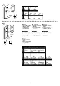
It is obligatory that there are spaces provided between the appliance and the
surrounding walls and the ceiling of the premise, as follow:
џ
For vertical
water
heaters – at least 70 mm between the appliance and
the ceiling; at least 50 mm between the appliance and the side wall; at
least 350 mm below the appliance to facilitate servicing and possible
repair.
џ
For horizontal
water
heaters – at least 70 mm between the unit and the
ceiling; at least 70 mm between the side cover (outlets excluded) and
the wall; at least 350 mm between the electric part plastic cover and
the wall to facilitate the servicing and possible repair, and a sufficient
distance below the unit for installation of water connections and drain
the water from the tank.
џ
In tanks with heat exchangers must be kept a distance from the coil
terminals side and the joints for additional thermostats necessary to
connect the additional control and safety units.
Water heater should be installed steadily on the wall of the premises. For this
purpose steel bolts (studs), tightly fixed in the wall, with diameter 10-12 mm
are used. The fixing elements should be secured against pulling aside the
wall – they should be anchor or passage bolts (depending of the wall
construction material). It is recommended that the elements on which the
heater will be suspended are designed for three times greater loads than the
appliance total weight and located in the water therein. Installation of the
water heater on decorative walls (made of single bricks or of other light
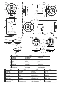
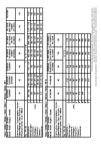
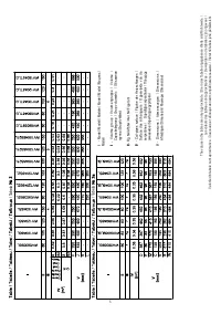
materials) is strictly forbidden. On Fig. 1,2,3,7 and in the tables are shown
the distances between the bolts (studs) for mounting the units.
Vertical water
heaters of 150 liters are equipped with special type of suspension plates and
correspondingly the distance between the bolts (studs) differs from that of
other models and modifications, please refer to Fig. 1.
WARNING!
The bearing plates of horizontal water heaters must be
securely clamped to the premise wall. Under the bolts heads (nuts on
studs) must be placed support washers!
Given the greater weight for water heaters of 150 liters there are higher
requirements for fixing to the premise wall and to the wall itself:
џ
Given the wall type, material and strength, in order to provide secure
attachment for vertical water heaters it is necessary to build an
additional structure or to take adequate measures to strengthen an
existing one. Samples of such constructions are shown on Fig. 15 for
reinforced concrete wall thick 25 cm and more, and on Fig. 16 - for
brick wall and others materials.
WARNING!
Non observance of the requirements for fixing the water
heater on the wall may cause damages of the appliance, damages on
other appliances and the premises, where the device is located, as well
as corrosion of the casing or even more serious failures and damages. In
such cases eventual failures and damages are not a subject to
manufacturer and seller warranty liabilities and will be at the expense of
the party which has not observed the present manual instructions.
The water heater mounting to the premise wall must be completed only by a
specialist.
WATER HEATER CONNECTION TO THE WATER
SUPPLY NETWORK
The plumbing to which the water heater will be connected, as well as any other
elements included in it shall have to withstand sustained water temperatures
above 80°C and for short periods - above 100°C, as well as to pressure at least
twice high the appliance working pressure.
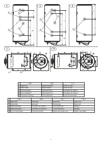
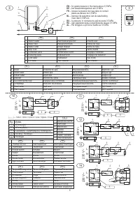
Upon connection of the water heater to the water supply grid, the arrows and
indication rings around the water heater pipes for hot and cold water must be
observed (inlet and outlet pipes). With an arrow towards the pipe and blue
color is marked the cold water pipe and an arrow starting from the pipe in red
color - the hot water pipe. Some appliances pipes are additionally marked
with badges. The pipes outlets are with threading 1/2". A schematic diagram
for water heater connection is shown on Fig 8. When the water heater works
at the water pipe tank pressure and that of the safety valve. In the event
where the conduit pressure is greater than 0,5 MPa it shall be required the
installation of reduce valve (pressure-reducing valve). Where local
regulations require use of additional devices that are not included with the
unit supply set and are not placed in the packaging, these must be
purchased and installed according to regulations.
The water heater is equipped with a combined non-return-safety valve. The
latter is located in the packaging of the appliance and MUST OBLIGATORY
be mounted on the cold water pipe. During that installation the arrow on its
hull showing the direction of water flow through the valve must be followed.
WARNING!
The absence or improper installation of the combined valve
supplied with the product is grounds for voiding the product warranty.
WARNING!
It is FORBIDDEN to install any kind of shut-off fittings
between the combined valve and the water heater! It is absolutely
forbidden to obstruct the lateral opening of the combined valve and/or to
block its lever!
Where the plumbing pipes are copper or of another metal, other than that of
the water tank, or where brass fasteners are used,
to install on
it is
obligatory
the water tank inlet and outlet non-metallic couplings (dielectric fittings).
ATTENTION!
For units with heat exchangers. Any additional tubular
outlets (excluding those of the serpentines) that will be connected with the
plumbing, and the holes for additional thermostats and / or
thermomanometer must be closed with a package insert or other suitable
for the purpose. The connections must be sealed for a water pressure of at
least 1.6 M
P
a.
It is recommended to set up a draining system for any dripping from the
combined valve side opening. The draining pipe must have a constant
downward slope and located in frost secure environment and its ends to be
constantly kept open to the atmosphere.
Once the water heater is connected to the water supply main, its water tank
should be filled up with water. It is carried out in the following order:
џ
Open completely the turn-cock for hot water of the most distant mixing
tap.
џ
Open the stop valve on pos. 4 from Fig. 8.
џ
Wait for the air from the system to come out and over half a minute
from the fitting outlet to flow out a thick and strong water stream.
џ
Close the turn-cock for hot water of the mixing tap.
џ
lift the lever of the combined valve on pos. 5 from Fig. 8 and wait for
about 30-60 seconds until a thick and powerful stream of water runs
out from the valve side opening.
џ
Loose the lever of the combined valve.
WARNING!
If no water is coming out of the opening of the combined
valve or the flow is weak (during normal water pressure), this should be
considered as a malfunction indicating that impurities from the plumbing
or caused by sewage connections have blocked the safety valve of the
combined valve.
IT IS FORBIDDEN
to proceed with appliance electric connection before
eliminating the reason for malfunction!
WARNING!
Failure to comply with the requirements for connection to
the water supply system may cause partial filling up of the water tank and
malfunction of the heating element, or when the combined valve is not
installed at all or has been improperly installed this may even cause
destruction of the water tank, the room and/or other damages to tangible
and intangible property. Such consequences are not within the scope of
manufacturer or seller warranty liabilities and shall be at the expense of
the party, which has not observed the present manual instructions.
WARNING!
The combined reciprocating safety valve is one of the unit
safety components ensuring security for water heater users. It is
specifically FORBIDDEN to use the water heater with a defective or
removed/unmounted combined safety valve!
The water heater connection to the water supply system must be performed
only by qualified persons.
Where necessary the safety valve may serve for draining the water out of the
10
EN
EN
Содержание
- 42 БЕЗОПАСНОСТЬ, ОСНОВНЫЕ ТРЕБОВАНИЯ; Подключение водонагревателя с встроенными теплообменниками к
- 43 Водонагреватели для вертикальной установки.
- 46 ИСПОЛЬЗОВАНИЕ ВОДОНАГРЕВАТЕЛЯ
- 47 В о д о н а г р е в а т е л ь с э м а л и р о в а н н ы м б а к о м .; Водонагреватель с эмалированным баком и анодным тестером.; П Р Е Д У П Р Е Ж Д Е Н И Е !
- 48 НЕИСПРАВНОСТИ


