Шлифмашины Bosch GWS 18 125 V LI 2×4 0Ah - инструкция пользователя по применению, эксплуатации и установке на русском языке. Мы надеемся, она поможет вам решить возникшие у вас вопросы при эксплуатации техники.
Если остались вопросы, задайте их в комментариях после инструкции.
"Загружаем инструкцию", означает, что нужно подождать пока файл загрузится и можно будет его читать онлайн. Некоторые инструкции очень большие и время их появления зависит от вашей скорости интернета.


20
| English
1
6
0
9
92
A 01F | (10.1.13)
Bosch Power Tools
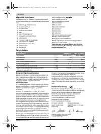
Note:
The battery is supplied partially charged. To ensure full
capacity of the battery, completely charge the battery in the
battery charger before using your power tool for the first time.
The Lithium-Ion battery can be charged at any time without
reducing its service life. Interrupting the charging procedure
does not damage the battery.
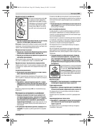
The Lithium-Ion battery is protected against deep discharging
by the “Electronic Cell Protection (ECP)”. When the battery is
empty, the machine is switched off by means of a protective
circuit: The inserted tool no longer rotates.
Do not continue to press the On/Off switch after the
machine has been automatically switched off.
The bat-
tery can be damaged.
The battery is equipped with a NTC temperature control
which allows charging only within a temperature range of be-
tween 0 ° C and 45 ° C. A long battery service life is achieved
in this manner.
Observe the notes for disposal.
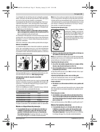
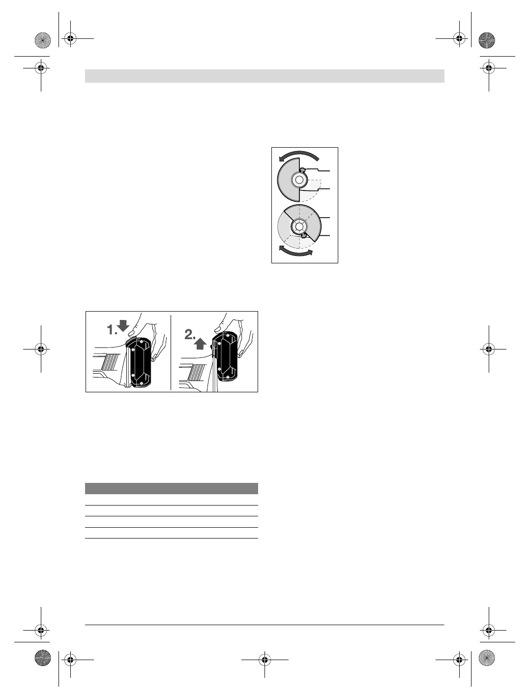
Removing the battery
The battery
5
is equipped with two locking levels that should
prevent the battery from falling out when pushing the battery
unlocking button
6
unintentionally. As long as the battery is
inserted in the power tool, it is held in position by means of a
spring.
To remove the battery
5
, press the unlocking button
6
and
pull out the battery toward the front.
Do not exert any force.
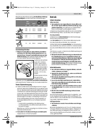
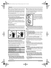
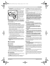
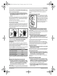
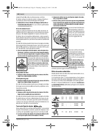
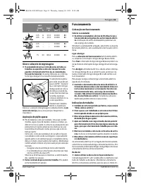
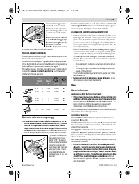
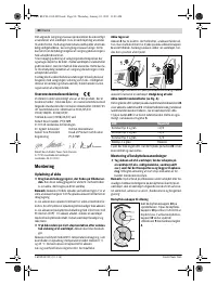
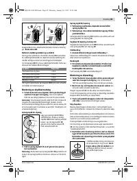
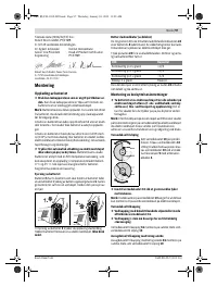
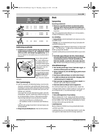
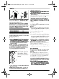
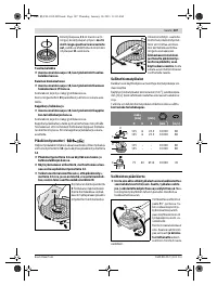
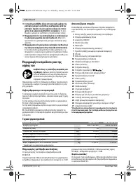
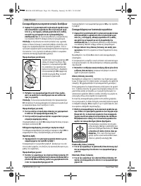
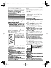
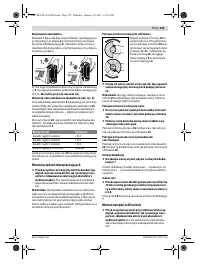
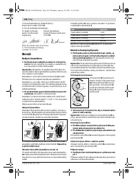
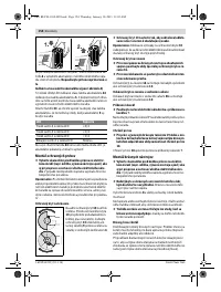
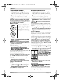
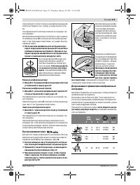
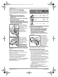
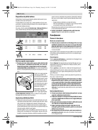
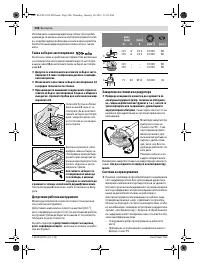
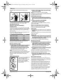
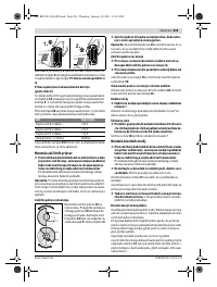
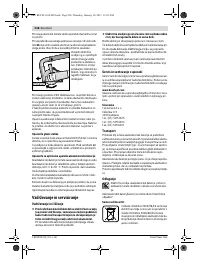
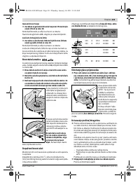
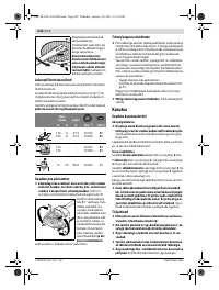
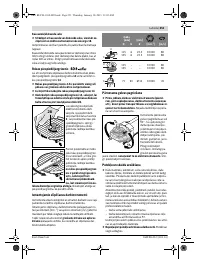
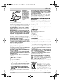
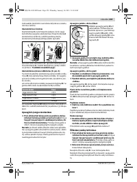
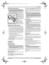
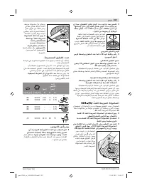
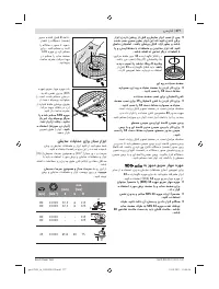
Battery Charge-control Indication (see figure A)
The three green LEDs of the battery charge-control indicator
24
indicate the charge condition of the battery
5
. For safety
reasons, it is only possible to check the status of the charge
condition when the machine is at a standstill.
Press button
23
to indicate the charge condition. This is also
possible when the battery
5
is removed.
When no LED lights up after pushing button
23
, then the bat-
tery is defective and must be replaced.
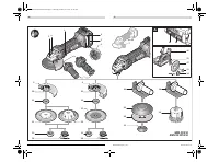
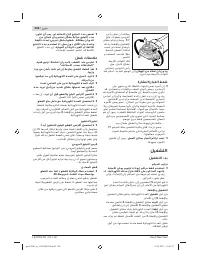
Mounting the Protective Devices
Before any work on the machine itself (e. g. mainte-
nance, tool change, etc.) as well as during transport
and storage, remove the battery from the power tool.
There is danger of injury when unintentionally actuating
the On/Off switch.
Note:
After breakage of the grinding disc during operation or
damage to the holding fixtures on the protection guard/power
tool, the machine must promptly be sent to an after-sales ser-
vice agent for maintenance for addresses, see section “After-
sales Service and Application Service”.
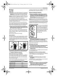
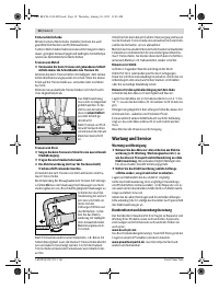
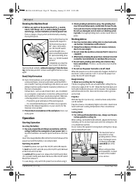
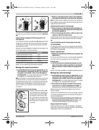
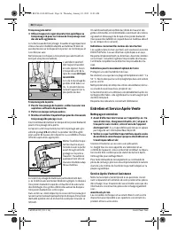
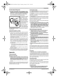
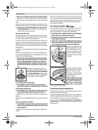
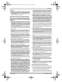
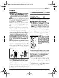
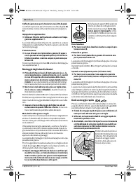
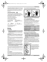
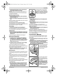
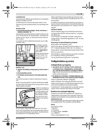
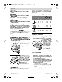
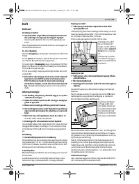
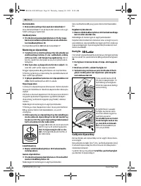
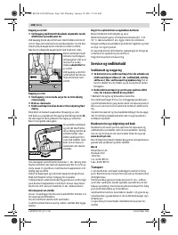
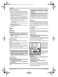
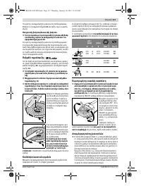
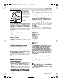
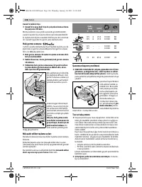
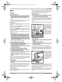
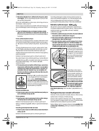
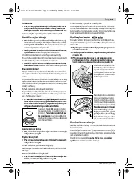
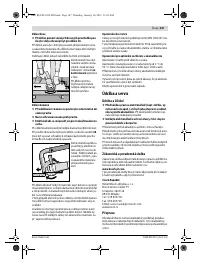
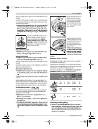
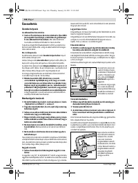
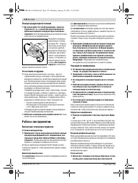
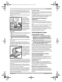
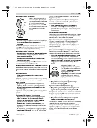
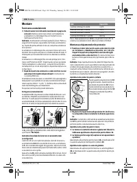
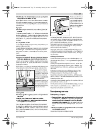
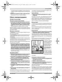
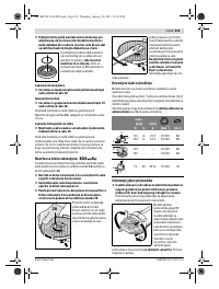
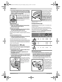
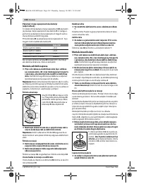
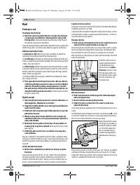
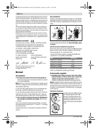
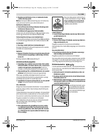
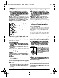
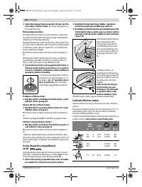
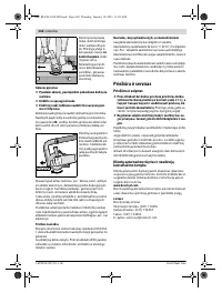
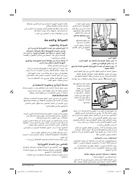
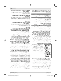
Protection Guard for Grinding
Place the protection guard
10
on
the spindle collar. Adjust the posi-
tion of the protection guard
10
to
the requirements of the operation.
Lock the protection guard
10
tight-
ening the locking screw
9
with an al-
len key
4
.
Adjust the protection guard 10 in such a manner that
sparking is prevented in the direction of the operator.
Note:
The encoding keys on the protection guard
10
ensure
that only a protection guard that fits the machine type can be
mounted.
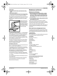
Protection Guard for Cutting
For cutting with bonded abrasives, always use the pro-
tection guard for cutting 16.
Provide for sufficient dust extraction when cutting
stone.
The protection guard for cutting
16
is mounted in the same
manner as the protection guard for grinding
10
.
Cutting Guide with Dust Extraction Protection Guard
The cutting guide with dust extraction protection guard
26
is
mounted in the same manner as the protection guard for
grinding
10
.
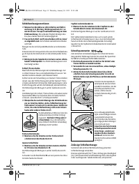
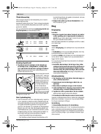
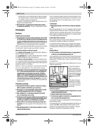
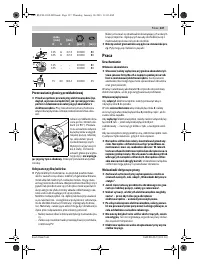
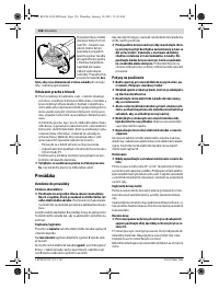
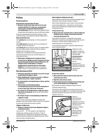
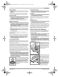
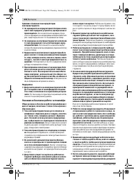
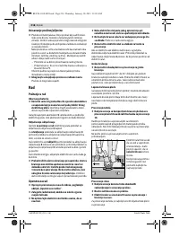
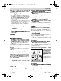
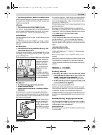
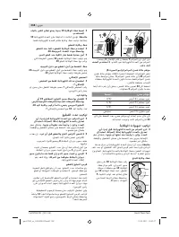
Auxiliary Handle
Operate your machine only with the auxiliary handle 7.
Screw the auxiliary handle
7
on the right or left of the machine
head depending on the working method.
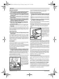
Hand Guard
For operations with the rubber sanding plate 19 or with
the cup brush/wheel brush/flap disc, always mount the
hand guard 18.
The hand guard
18
is fastened with the auxiliary handle
7
.
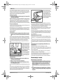
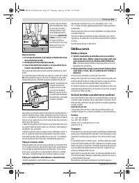
Mounting the Grinding Tools
Before any work on the machine itself (e. g. mainte-
nance, tool change, etc.) as well as during transport
and storage, remove the battery from the power tool.
There is danger of injury when unintentionally actuating
the On/Off switch.
Do not touch grinding and cutting discs before they
have cooled down.
The discs can become very hot while
working.
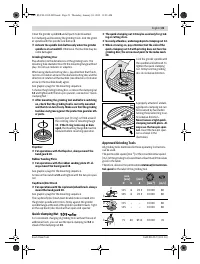
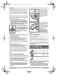
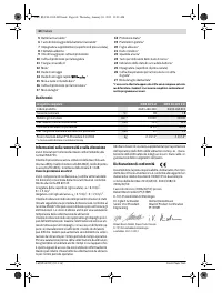
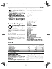
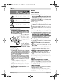
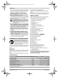
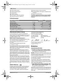
LED
Capacity
Continuous lighting 3 x green
2
/3
Continuous lighting
2
x green
1/3
Continuous lighting 1 x green
< 1/3
Flashing light 1 x green
Reserve
OBJ_BUCH-1102-005.book Page 20 Thursday, January 10, 2013 11:03 AM


