
Котел De Dietrich MS 24 MI FF - инструкция пользователя по применению, эксплуатации и установке на русском языке. Мы надеемся, она поможет вам решить возникшие у вас вопросы при эксплуатации техники.
Если остались вопросы, задайте их в комментариях после инструкции.
"Загружаем инструкцию", означает, что нужно подождать пока файл загрузится и можно будет его читать онлайн. Некоторые инструкции очень большие и время их появления зависит от вашей скорости интернета.


79
71.03982.03 - EN
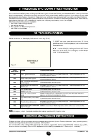
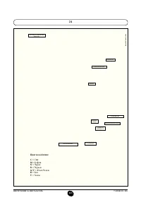
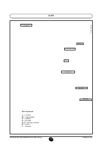
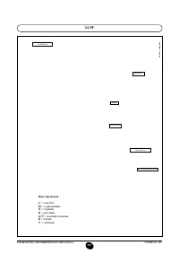
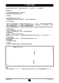
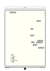
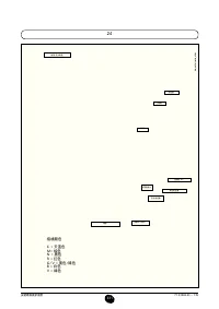
INSTALLATION INSTRUCTIONS
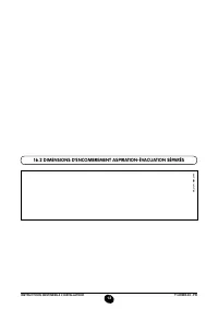
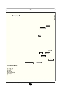
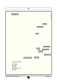
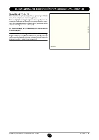
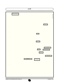
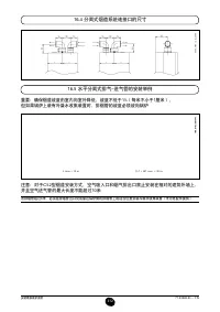
… SEPARATE FLUE AND AIR DUCTS
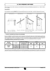
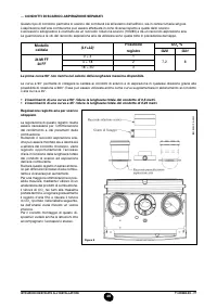
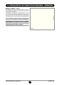
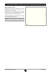
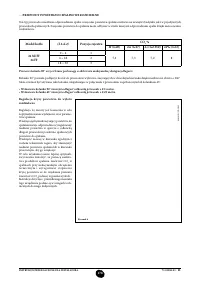
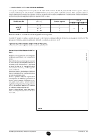
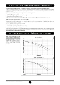
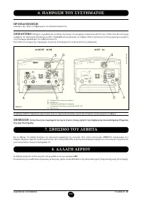
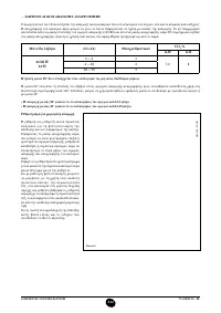
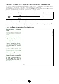
This type of installation makes it possible to discharge exhaust fumes both outside the building and into single lue ducts.
Comburent air can be drawn in at a different location from that of the lue terminal. The splitting kit comprises a lue duct
adaptor (100/80) and an air duct adaptor. For the air duct adaptor, it the screws and seals previously removed from the cap.
The 90° curve allows the boiler to be connected to a lue-air duct in any direction as it can be rotated by 360°. It can also
be used as a supplementary curve combined with a duct or a 45° curve.
• A 90° curve reduces total duct length by 0.5 metres.
• A 45° curve reduces total duct length by 0.25 metres.
The first 90° curve is not considered when calculating the maximum available length.
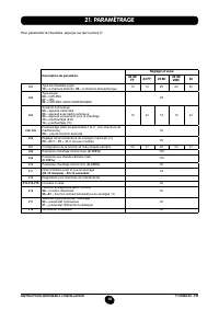
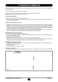
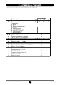
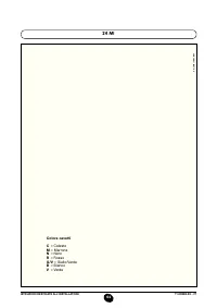
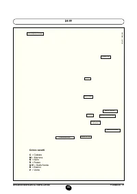
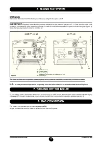
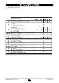
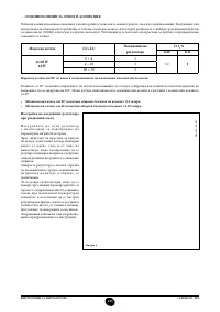
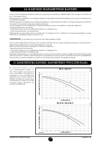
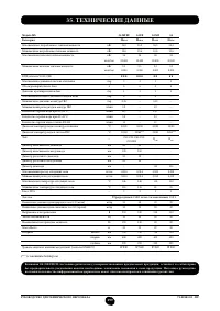
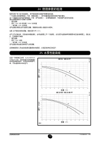
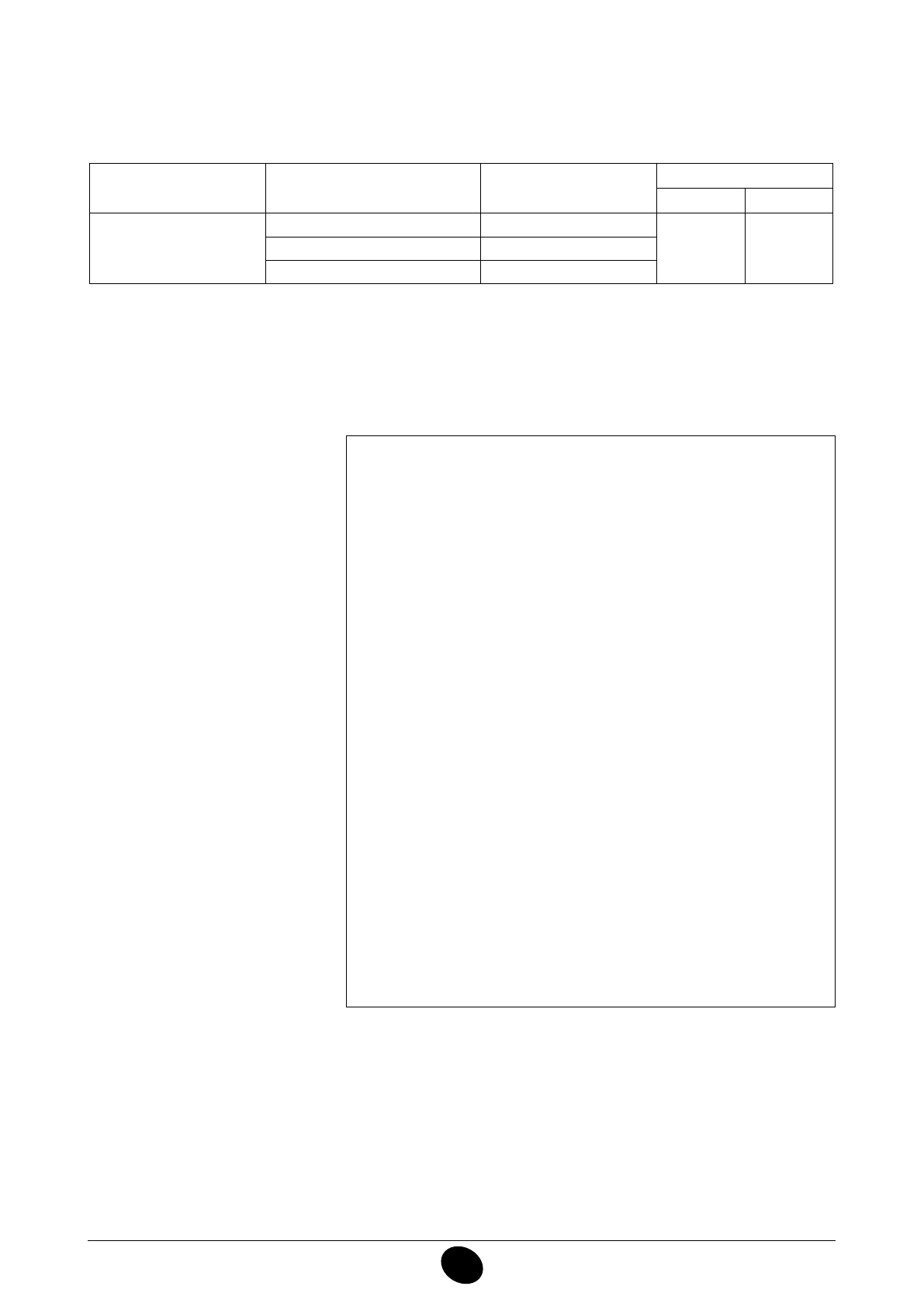
Boiler model
(L1+L2)
Position
of air regulator
CO
2
%
G20
G31
24 MI FF
24 FF
0 ÷ 4
1
7,2
8
4 ÷ 18
2
18 ÷ 30
3
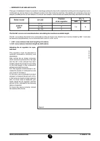
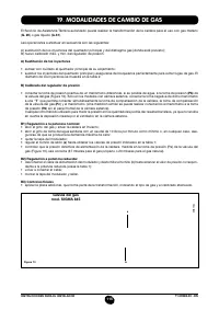
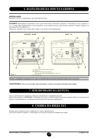
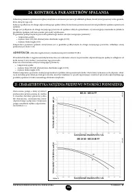
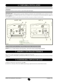
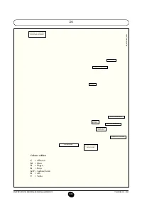
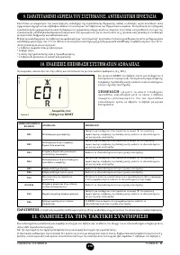
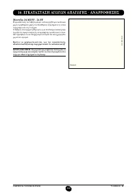
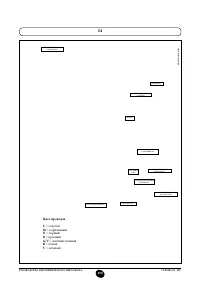
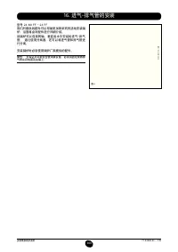
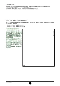
Adjusting the air regulator for sepa-
rate flues
This regulator must be adjusted to
optimise combustion efficiency and
parameters.
After turning the air intake connecter,
which can be mounted both to the right
and the left of the exhaust lue duct,
suitably adjust the excess air according
to the total length of the combustion
exhaust and inlet lue ducts.
Turn this regulator anticlockwise to de-
crease the excess of comburent air and
vice-versa to increase it.
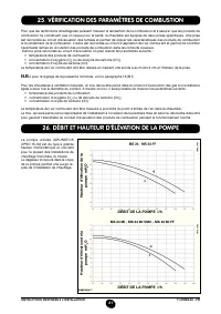
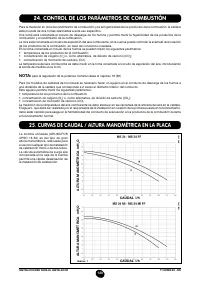
To ine tune, use a combustion product
analyser to measure the amount of CO
2
in the fumes at maximum heat capacity,
and, if a lower value is measured, gra-
dually adjust the air regulator until the
amount of CO
2
indicated in the following
table is measured.
To mount this device correctly, consult
the relative instructions
.
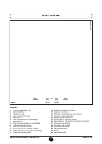
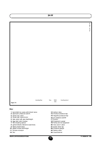
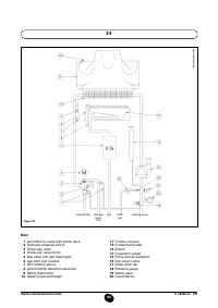
Figure 8
0809_0201 / CG_2045
Содержание
- 267 Уважае
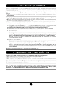
- 268 ПОДГОТОВКА К УСТАНОВКЕ
- 271 ВЫКЛЮЧЕНИЕ КОТЛА; ЗАПОЛНЕНИЕ СИСТЕМЫ
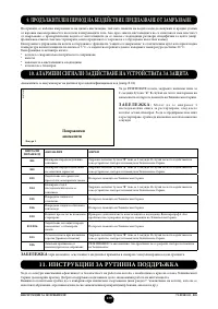
- 272 СИСТЕМА БЕЗОПАСНОСТИ: ИНДИКАТОРЫ И СРАБАТЫВАНИЕ; ВЫКЛЮЧЕНИЕ НА ДЛИТЕЛЬНЫЙ ПЕРИОД. ЗАЩИТА ОТ ЗАМЕРЗАНИЯ; Неисправность
- 273 ПРОВЕРКИ ПЕРЕД УСТАНОВКОЙ КОТЛА
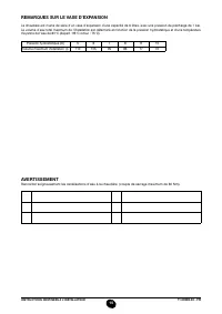
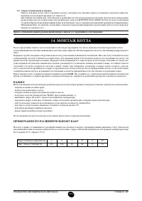
- 274 ПРИМЕЧАНИЕ ПО РАСШИРИТЕЛЬНОМУ БАКУ
- 276 УСТАНОВКА ДЫМОХОДА И ВОЗДУХОВОДА
- 277 ВАРИАНТЫ ГОРИЗОНТАЛЬНОЙ УСТАНОВКИ НАКОНЕЧНИКА ДЫМОХОДА
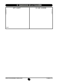
- 278 Модель котла
- 280 ПОДКЛЮЧЕНИЕ К ЭЛЕКТРОПИТАНИЮ; Внимание
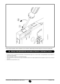
- 281 ПОДСОЕДИНЕНИЕ КОМНАТНОГО ТЕРМОСТАТА
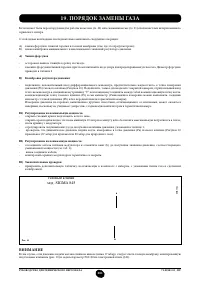
- 282 ПОРЯДОК ЗАМЕНЫ ГАЗА; газовый клапан
- 283 ФУНКЦИЯ КАЛИБРОВКИ ГАЗОВОГО КЛАПАНА; Примечание
- 284 ВЫВОД ИНФОРМАЦИИ НА ДИСПЛЕЙ КОТЛА
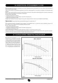
- 287 КОНТРОЛЬ ОТХОДЯЩИХ ГАЗОВ; ап
- 288 ПРИСОЕДИНЕНИЕ ДАТЧИКА УЛИЧНОЙ ТЕМПЕРАТУРЫ; СОЕДИНЕНИЕ НАРУЖНОГО БЛОКА БОЙЛЕРА
- 289 ЕЖЕГОДНОЕ ТЕХНИЧЕСКОЕ ОБСЛУЖИВАНИЕ
- 290 ОЧИСТКА ОТ ИЗВЕСТКОВОГО НАЛЕТА В СИСТЕМЕ ГВС
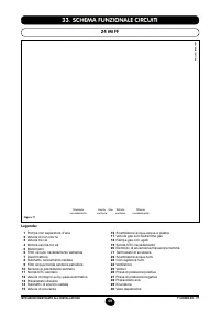
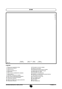
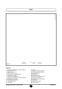
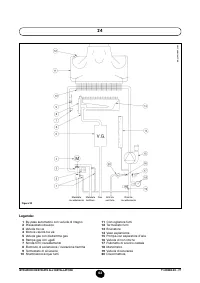
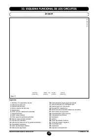
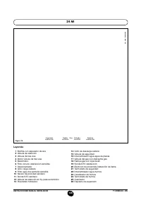
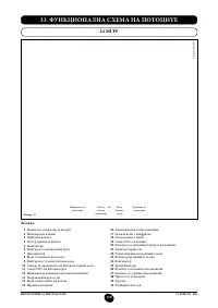
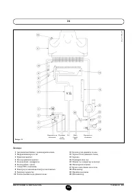
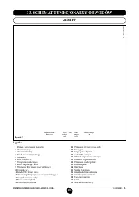
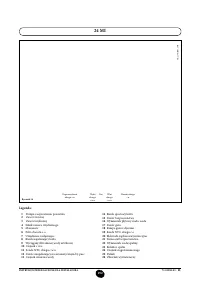
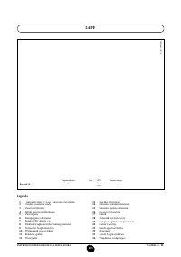
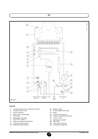
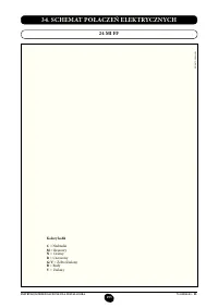
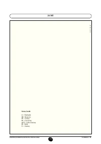
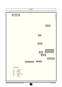
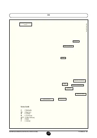
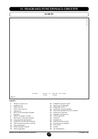
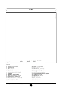
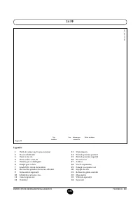
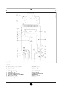
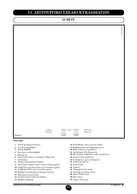
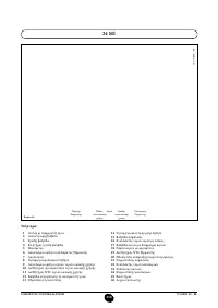
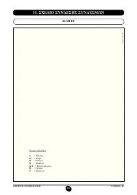
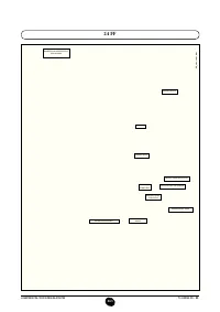
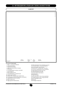
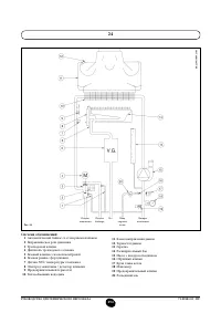
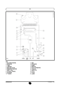
- 292 ФУНКЦИОНАЛЬНАЯ СХЕМА КОНТУРОВ
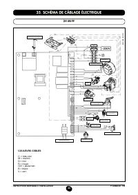
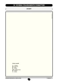
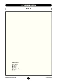
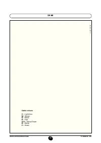
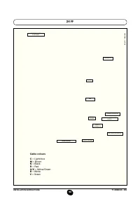
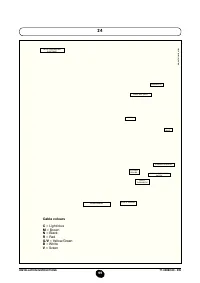
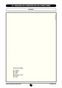
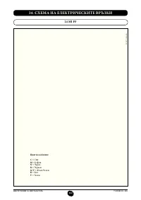
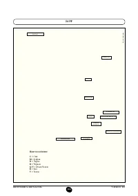
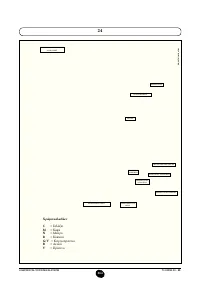
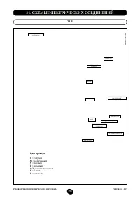
- 296 СХЕМЫ ЭЛЕКТРИЧЕСКИХ СОЕДИНЕНИЙ; Цвет проводов; олубой
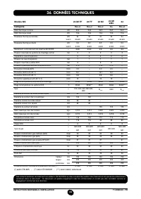
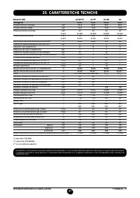
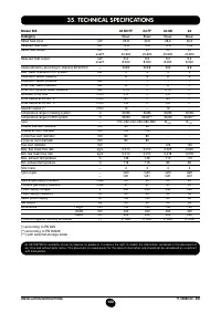
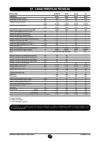
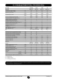
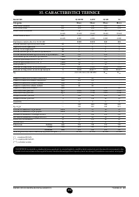
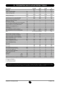
- 300 ТЕХНИЧЕСКИЕ ДАННЫЕ


Добрый день. Может ли газовый котел Дитрих 24 одноконтурный постоянно работать на электролите?