
Заточные станки Sparky MBGS 200 - инструкция пользователя по применению, эксплуатации и установке на русском языке. Мы надеемся, она поможет вам решить возникшие у вас вопросы при эксплуатации техники.
Если остались вопросы, задайте их в комментариях после инструкции.
"Загружаем инструкцию", означает, что нужно подождать пока файл загрузится и можно будет его читать онлайн. Некоторые инструкции очень большие и время их появления зависит от вашей скорости интернета.


6
EN
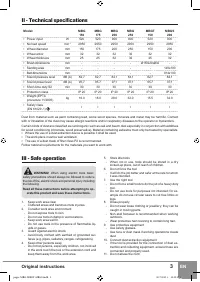
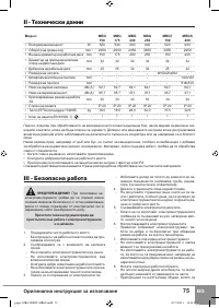
MBG 150/175/200/250
•
MBGT 150
•
MBGS 200
▪
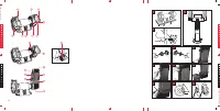
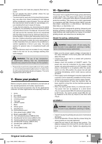
Mount the eye shield supports (3). During normal
operation the operator must have a clear view of the
grinding wheels (4) through the eye shields (2).
WARNING:
Never operate the bench grinder
without the wheel guards and the eye shields.
▪
After assembling the machine connect the dust port
(10) to a dust extraction system.
WHEEL REPLACEMENT
WARNING:
Always switch off and unplug the
power tool prior to any adjustment, servicing or mainte-
nance, including accessory replacement.
WARNING:
Use only grinding wheels with di-
mensions and peripheral speed, corresponding to the
specification of the bench grinder.
To replace a grinding wheel perform the following opera-
tions:
1. Inspect the new grinding wheel for visible defects.
Then insert your forefinger into the wheel arbor and
tap it gently with a light non-metallic object (for exam-
ple with a screwdriver handle or a mallet)
(Fig.3)
. The
sound emitted by the wheel should be clear and ring-
ing. A damaged wheel will respond with a dull thud; in
this case the wheel has inner cracks and defects and
must be discarded.
NOTE:
The wheel you intend to test must be dry. Damp
wheels emit a dull thud.
WARNING:
Never use damaged wheels!
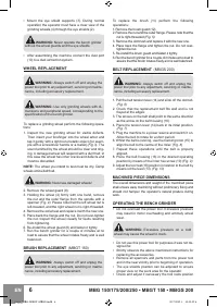
2. Remove the wheel guard (8).
3. Holding the wheel (4) firmly with one hand, remove
the nut and the outer flange from the spindle with a
spanner
(Fig. 4)
. Please note that the left wheel nut is
left-treaded, and the right wheel nut is right-threaded.
4. Remove the old wheel and replace it with the new one.
5. Place back the flange and the nut. Do not over-tighten
the nut. Inspect the wheel visually for faults resulting
from tightening.
6. Re-install the wheel guard (8) and fasten it tightly.
7. Run the bench grinder for a couple of minutes at no
load to assure that the wheel rotates freely and is well
balanced.
BRUSH REPLACEMENT
(MBGT 150)
WARNING:
Always switch off and unplug the
power tool prior to any adjustment, servicing or mainte-
nance, including accessory replacement.
To replace the brush (11) perform the following
operations:
1. Remove the brush guard (12).
2. Remove the nut and the outer flange. Please note that the
nut is right-threaded
(Fig. 5)
.
3. Remove the old brush and replace it with the new one.
4. Place back the flange and tighten the nut. Do not over-
tighten the nut.
5. Re-install the brush guard and fasten it tightly.
6. Run the bench grinder for a couple of minutes at no load to
assure that the brush rotates freely and is well balanced.
BELT REPLACEMENT
(MBGS 200)
WARNING:
Always switch off and unplug the
power tool prior to any adjustment, servicing or mainte-
nance, including accessory replacement.
1. Pull the belt tension lever (14) and slide off the old belt.
(Fig. 6)
2. Check that the replacement belt fits well and is not
frayed at the edges.
3. The arrows on the belt shall point to the same direction
as the arrow on the belt housing (16).
4. Place the tension lever (14) back in its initial position.
(Fig. 7)
5. Plug the machine to a power source and switch it on.
Allow the belt to rotate for a short period.
6. Whilst the belt is running, use the tracking knob (15) to
align the belt to the centre of the roller.
(Fig. 8)
7. Repeat these operations until the belt is properly
aligned.
8. Place the belt housing (16) in the desired operating
position by means of the inner hex screw (19)
(Fig. 9)
9. Adjust the tool rest (18) position in relation to the belt by
means od the lever (13).
(Fig. 10)
MACHINED PIECE DIMENSIONS
The overall dimensions and weight of the machined piece
shall ensure easy machining without preliminary fixing and
should not hamper the operator’s natural posture during
work.
OPERATING THE BENCH GRINDER
▪
Do not overload the power tool. Excessive pressure
may result in motor overheating and untimely wheel
wear.
WARNING:
Excessive pressure on a cold
wheel may cause the wheel to crack.
▪
Do not use this power tool for purposes it was not de-
signed for.
▪
Strictly observe the above mentioned instructions for
replacing the accessories.
▪
Remove all spanners and parts from the power tool
and in the near vicinity prior to beginning of operation.
▪
The eye shields position can be adjusted to ensure
proper view on the work area for the operator.
▪
Check and adjust if necessary the tool rests position
pages-MBG-MBGT-MBGS.indd 6
30.7.2012 г. 15:12:52 ч.
Характеристики

Остались вопросы?Не нашли свой ответ в руководстве или возникли другие проблемы? Задайте свой вопрос в форме ниже с подробным описанием вашей ситуации, чтобы другие люди и специалисты смогли дать на него ответ. Если вы знаете как решить проблему другого человека, пожалуйста, подскажите ему :)


