
Водонагреватели TESY GCU 1015 L52 RC 304141 - инструкция пользователя по применению, эксплуатации и установке на русском языке. Мы надеемся, она поможет вам решить возникшие у вас вопросы при эксплуатации техники.
Если остались вопросы, задайте их в комментариях после инструкции.
"Загружаем инструкцию", означает, что нужно подождать пока файл загрузится и можно будет его читать онлайн. Некоторые инструкции очень большие и время их появления зависит от вашей скорости интернета.


Instructions for use and maintenance
9
EN
English
V.
INSTALLATION AND SWITCH ON
Attention! Improper installation and connection of the
appliance may make it hazardous for the health and life
of consumers. It may cause grievous and permanent
consequences, including but not limited to physical injuries and/or
death. Improper installation and connection of the appliance may
also lead to damage to the consumers’ property /damage and/ or
destruction/, or to that of third persons, as a result of, but not
limited to flooding, explosion and/or fire.
Installation, connection to the main water and power supply, and
putting into operation must be carried out by certified electricians
and technical personnel certified in installation of this category of
appliances, who have obtained their license in the state where the
installation and commissioning of the appliance are carried out,
and in compliance with its local legislation.
1.
Installation
We recommend installation of the device at close proximity
to locations where hot water is used, in order to reduce heat
losses during water transportation. The selected location
must exclude the possibility of water spray originating from
the showerhead or other water contacts.
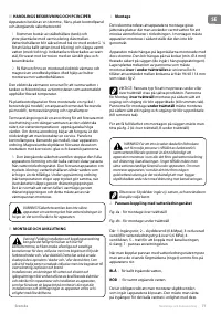
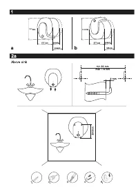
The appliance is affixed to a wall by means of mounting
brackets attached to the unit's body. Two hooks are used to
fix the appliance (min. Ø 4 mm) firmly on the wall (included
in the mounting set). The bearing plank construction for
boilers installed
above / under sinks
is universal and allows
the space between hooks to vary between 96 and 114mm.
(fig.2)
IMPORTANT: The type of boiler designed to be installed
UNDER / ABOVE a sink is marked on the appliance.
Boilers designed for installation
above sinks
are assembled in
such a manner that the outlet/inlet pipes are pointed
downwards (to the floor of the premise). Boilers designed for
installation
under sinks
are assembled in such a manner that
the outlet/inlet pipes are pointed upwards (to the ceiling of
the premise).
For clear understanding of wall installation schemes, please
refer to fig.2 (A above sink and B under sink).
ATTENTION! In order to prevent injury to user and
third persons in the event of faults in the hot water
supply system, the appliance must be mounted in premises
outfitted with floor hydro insulation and sewer drainage.
Don't place objects, which are not waterproof under the
appliance under any circumstances. In the event of mounting
the appliance in premises without floor hydro insulation, a
protective tank with a sewer discharge drainage must be
placed under the appliance.
Notice: the set does not include a protective tub and the
user must select the same.
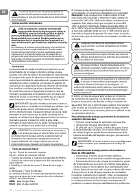
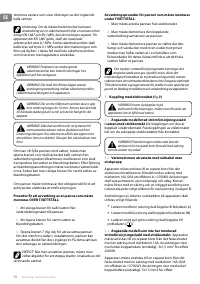
2.
Water heater connection to the water supply system
Fig.4a
- installation scheme above sink
Fig.4b
- installation scheme under sink
Where: 1 – input pipe, 2 – safety valve (0.8 MPa), 3 –
reduction valve (if the water supply pressure exceeds 0,6
MPa), 4 – stop valve, 5 – bell-mouth discharge to the sewer,
6 – hose; 7 - Drain water tap.
Upon connecting the water heater to the water supply
system, take care of the indicative color markings /rings/ of
the pipes:
BLUE
- for cold /in-flowing/ water,
RED
- for hot /out-flowig/ water.
The mounting of the safety return-valve supplied with the
water heater is obligatory. The safety return-valve must
be installed on the cold water supply pipe, according to
the arrow stamped on its body that indicates the supplied
water direction.
Exception: If the local regulations (norms) require the
usage of another protection valve or mechanism (in
accordance with EN 1487 or EN 1489), then it must be bought
additionally. For mechanisms operating in accordance with EN
1487 the announced operational pressure must be no more
than 0.7 MPa. For other protection valves, the pressure at which
they are calibrated must be 0.1 MPa lower than the one marked
on the appliance’s sign. In these cases the safety valve which the
appliance is supplied with should not be used
.
ATTENTION! Other type of stopping armature is not
allowed between the protection return valve (the
protective device) and the appliance.
ATTENTION! Any other /old/ safety return-valves may
lead to a failure of your appliance, therefore they
must be removed.
ATTENTION! Fixing the safety return-valve to threads
longer than 10 mm is not allowed, as it could
damaged the valve and could make the use of your
appliance dangerous.
ATTENTION! The safety valve and the pipe between
the valve and the water heater must be protected from
freezing. During hose draining - its free end must be always
open to the atmosphere (not to be immersed). Make sure that
the hose is also protected from freezing.
The boiler is filled with water by opening the tap on the cold
water supply system and the tap on the hot water mixing
faucet. After the filling process is complete, a constant
stream of water should flow from the water-mixing faucet.
Now you can shut the hot water tap on the mixing faucet.
When you must empty the water heater, you should first cut
it off the power supply.
Draining procedure for boilers designed to be installed
ABOVE SINKS:
1.
First shut the cold water supply valve
2.
Open the hot water valve on the mixing-faucet
3.
The water tap 7 (
fig 4a
) must be opened to drain the
water from water tank. If there is no such tap build in the
pipe line, than the water can be drain directly from inlet
pipe of water tank after when you disconnect it from
water main
IMPORTANT: When draining the boiler, take measures
to prevent damages caused by the flowing water.
Draining procedure for boilers designed to be installed
UNDER SINKS:
1.
Switch the boiler off the power supply network.
2.
Dismantle the connecting water fittings from the boiler.
3.
Disassemble the boiler from its installation place, turn
it so the pipes point to the floor and pour the water in a
vessel you have prepared for the purpose. Wait until all
the water drains out of the boiler.
In case that the pressure in the water mains is over the value
pointed out in the above paragraph I, then it is necessary
to assemble a pressure reduce valve, otherwise the water
heater would not function properly. The Manufacturer does
not assume any liability for problems arising out of the
appliance’s improper use.

