
Шуруповерты GRAPHITE Energy+ 18 V 58G020 - инструкция пользователя по применению, эксплуатации и установке на русском языке. Мы надеемся, она поможет вам решить возникшие у вас вопросы при эксплуатации техники.
Если остались вопросы, задайте их в комментариях после инструкции.
"Загружаем инструкцию", означает, что нужно подождать пока файл загрузится и можно будет его читать онлайн. Некоторые инструкции очень большие и время их появления зависит от вашей скорости интернета.


14
15
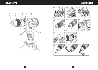
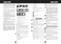
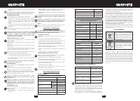
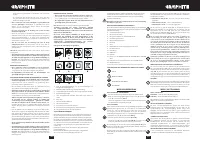
BAT TERY LEVEL INDICATION
The battery is equipped with signalisation of the battery level (3
LED diodes) (
14
). To check battery level status, press the button
for battery level indication (
13
) (
fig. C
). When all diodes are lit,
the battery level is high. When 2 diodes are on, the battery is
partially discharged. When only one diode is lit, the battery is
discharged and must be recharged.
SPINDLE BRAKE
Drill is equipped with electronic brake that stops the spindle
immediately after the switch button (
9
) is released. The brake
ensures precision when screwing or drilling and prevents free
spindle rotation after switching off.
OPERATION / SET TINGS
SWITCHING ON / SWITCHING OFF
Switching on
– press the switch button (
9
).
Switching off
– release the switch button (
9
).
Each time the switch button (
9
) is pressed, the LED diode (
10
)
lights up to illuminate the workplace.
ROTATIONAL SPEED CONTROL
Increase or reduce pressure on the switch button (
9
) to adjust
drilling or driving speed while operating. Speed adjustment
allows for a soft start, which prevents dill slipping when drilling
holes in gypsum or glaze, and allows for operation control when
driving screws in and out.
OVERLOAD CLUTCH
Set the torque adjustment ring (
3
) in appropriate position
to permanently set overload clutch to defined torque value.
When the set torque is reached, overload clutch disconnects
automatically. It prevents from driving screws too deep or
damaging the drill.
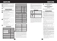
TORQUE ADJUSTMENT
•
Different screws and materials require different torque to be
applied.
•
The bigger the number corresponding to given position, the
bigger is the torque (
fig. D
).
•
Set the torque adjustment ring (
3
) to appropriate torque value.
•
Always start operation with low torque.
•
Increase the torque gradually until obtaining desired results.
•
Use higher settings to undo screws.
•
When drilling, choose setting marked with the drill symbol.
The torque is the greatest with this setting.
•
Knowledge how to choose appropriate torque setting comes
with practice.
Setting the torque adjustment ring in the drilling position
deactivates the overload clutch.
WORKING TOOL INSTALLATION
•
Set the direction selector switch (
5
) in the middle position.
•
By turning the ring of the quick release chuck (
2
) counter
clockwise (see mark on the ring) you can spread jaws enough
to insert drill or driver bit (
fig. E
).
•
To fix the working tool, turn the ring of the quick release chuck
(
2
) clockwise and tighten.
Deinstallation of the tool is similar to installation, only the
sequence of actions is reversed.
Make sure the tool position is correct when installing drill or
driver bit in the quick release chuck. Use additional magnetic
adapter as an extension when using short driver bits.
RIGHT-LEFT DIRECTION OF ROTATION
Choose direction of spindle rotation with the direction selector
switch (
5
) (
fig. F
).
Clockwise rotation
– set the switch (
5
) to the extreme left
position.
Counter-clockwise rotation
– set the switch (
5
) to the extreme
right position.
* In certain cases position of the switch related to rotation may be different
than specified. Please refer to graphic signs located on the switch or tool
body.
Safe position of the direction selector switch (
5
) is in the middle,
it prevents accidental starting of the power tool.
•
Drill cannot be started, when the switch is in this position.
•
Use this position of the switch to change drills or bits.
•
Before starting the tool make sure the position of the direction
selector switch (
5
) is correct.
Do not change direction of rotation when the drill spindle
is rotating.
CHANGE OF GEAR
Gear switch (
4
) (
fig. H
) allows to increase the range of rotational
speed.
Gear I:
small speed range, big torque
Gear II:
greater speed range, small torque.
Set the gear switch in position appropriate for the works to
perform. When the switch is blocked and cannot be moved, turn
the spindle slightly.
Never change the gear switch position when the drill is
operating. It may damage the power tool.
Long lasting drilling at low rotational speed of the spindle
may cause motor overheating. Long lasting drilling at
low rotational speed of the spindle may cause motor
overheating.
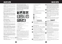
OPERATION MODE SWITCH
Operation mode selection ring (
15
) (
fig. I
) allows to select the
tool function:
• Screw symbol
– operation with overload clutch active
• Drill symbol
– drilling. The highest torque is available
(overload clutch deactivated).
• Hammer symbol
– impact drilling (overload clutch
deactivated).
Setting the operation mode selection ring in the position for
drilling or impact drilling deactivates the overload clutch.
Do not try to change position of the operation mode
selection ring when the tool spindle is rotating. Such action
can cause serious damage of the power tool.
HOLDER
The drill provides convenient holder (
6
) that allows to e.g. hang
the tool on a tool belt when working at heights.
OPERATION AND MAINTENANCE
Remove the battery from the device before commencing
any activities related to installation, adjustment, repair or
maintenance.
MAINTENANCE AND STORAGE
•
Cleaning the device after each use is recommended.
•
Do not use water or any other liquid for cleaning.
•
Clean the tool with a dry cloth or blow through with
compressed air at low pressure.
•
Do not use any cleaning agents or solvents, they may damage
plastic parts.
•
Clean ventilation holes in the motor casing regularly to
prevent device overheating.
•
Always store the tool in a dry place, beyond reach of children.
•
Store the device with the battery removed.
QUICK RELEASE CHUCK REPLACEMENT
Quick-release chuck is screwed onto spindle of the drill and
additionally secured with a screw.
•
Set the direction selector switch (
5
) in the middle position.
•
Open jaws of quick release chuck (
1
) and unscrew the fixing
screw (left-hand thread) (
fig. H
).
•
Install hexagonal key in the quick release chuck and tap the
other end of the key.
•
Unscrew the quick release chuck.
•
Installation of the quick release chuck is similar to
deinstallation, only the sequence of actions is reversed.
All defects should be repaired by service workshop authorized
by the manufacturer.
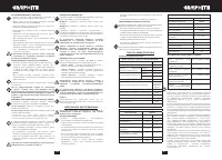
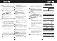
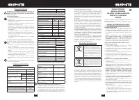
TECHNICAL PARAMETERS
RATED PARAMETERS
Cordless drill with impact 58G020
Parameter
Value
Battery voltage
18 V DC
Range of idle rotational speed
gear I
0-500 min
-1
gear II
0-1700 min
-1
Impact speed on idle
gear I
0-7500 min
-1
gear II
0-25500 min
-1
Range of quick release chuck
2-13 mm
Torque control range
1–16 + drilling,
impact drilling
Max. torque (soft drive)
38 Nm
Max. torque (hard drive)
58 Nm
Protection class
III
Weight
1,2 kg
Year of production
2018
58G020 defines type and indication of the device
Graphite Energy+ System Battery
Parameter
Value
Battery
58G001
58G004
Battery voltage
18 V DC
18 V DC
Battery type
Li-Ion
Li-Ion
Battery capacity
2000 mAh
4000 mAh
Ambient temperature range
4
0
C – 40
0
C
4
0
C – 40
0
C
Charging time for charger 58G002
1 h
2 h
Weight
0,400 kg
0,650 kg
Year of production
2018
2018
Graphite Energy+ System Charger
Parameter
Value
Charger type
58G002
Supply voltage
230 V AC
Power supply frequency
50 Hz
Charging voltage
22 V DC
Max. charging current
2300 mA
Ambient temperature range
4
0
C – 40
0
C
Charging time of the battery 58G001
1 h
Charging time of the battery 58G004
2 h
Protection class
II
Weight
0,300 kg
Year of production
2018
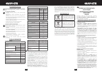
NOISE LEVEL AND VIBRATION PARAMETERS
Sound pressure (drilling)
Lp
A
= 77,5 dB(A) K= 3 dB(A)
Sound pressure (drilling with
impact)
Lp
A
= 85,5 dB(A) K= 3 dB(A)
Sound power (drilling)
Lw
A
= 88,5 dB(A) K= 3 dB(A)
Sound power (drilling with
impact)
Lw
A
= 96,5 dB(A) K= 3 dB(A)
Vibration acceleration (drilling)
a
h
= 2,04 m/s
2
K= 1,5 m/s
2
Vibration acceleration (drilling
with impact)
a
h
= 11,72 m/s
2
K= 1,5 m/s
2
Noise and vibration information
Noise produced by the device is defined with: level of produced
sound pressure Lp
A
and level of sound power Lw
A
(where K is
measurement uncertainty). Vibrations produced by the device
are defined with vibration acceleration value a
h
(where K is
measurement uncertainty).
Sound pressure Lp
A
, sound power Lw
A
and vibration acceleration
ah specified in this manual have been measured in accordance
with EN 60745-1. Specified vibration level a
h
can be used
to compare tools and for initial evaluation of exposition to
vibrations.
Specified vibration level is representative for main applications
of the device. When the device is used for other purposes or
with different working tools, the vibration level may change.
Insufficient or too rare maintenance may increase vibration
level. The abovementioned factors may lead to higher exposure
to vibrations during whole working time.
To precisely define exposure to vibrations, include periods
when the device is switched off and when it is switched on
but not used for working. Once all factors have been carefully
considered, total exposition to vibrations may be significantly
lower.
To protect the user from results of exposure to vibrations, use
additional safety measures such as: device and working tool
periodic maintenance, proper hand temperature conditions,
good work organisation.


