Пилы торцовочные Makita MLS100 - инструкция пользователя по применению, эксплуатации и установке на русском языке. Мы надеемся, она поможет вам решить возникшие у вас вопросы при эксплуатации техники.
Если остались вопросы, задайте их в комментариях после инструкции.
"Загружаем инструкцию", означает, что нужно подождать пока файл загрузится и можно будет его читать онлайн. Некоторые инструкции очень большие и время их появления зависит от вашей скорости интернета.


11
5.
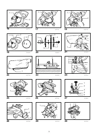
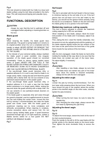
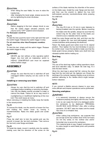
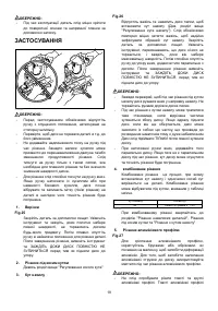
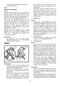
Cutting aluminum extrusion
Fig.27
When securing aluminum extrusions, use spacer
blocks or pieces of scrap as shown in the figure to
prevent deformation of the aluminum. Use a
cutting lubricant when cutting the aluminum
extrusion to prevent build-up of the aluminum
material on the blade.
CAUTION:
•
Never attempt to cut thick or round aluminum
extrusions. Thick aluminum extrusions may come
loose during operation and round aluminum
extrusions cannot be secured firmly with this tool.
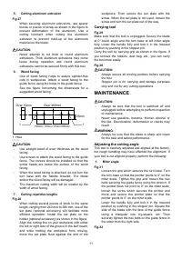
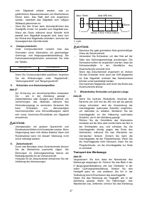
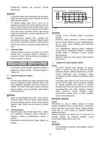
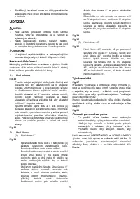
6. Wood
facing
Use of wood facing helps to assure splinter-free
cuts in workpieces. Attach a wood facing to the
guide fence using the holes in the guide fence.
See the figure concerning the dimensions for a
suggested wood facing.
Over 10mm
Over 460mm
1
1
25mm
100mm 115mm
100mm
115mm
007833
CAUTION:
•
Use straight wood of even thickness as the wood
facing.
•
Use screws to attach the wood facing to the guide
fence. The screws should be installed so that the
screw heads are below the surface of the wood
facing.
•
When the wood facing is attached, do not turn the
turn base with the handle lowered. The blade
and/or the wood facing will be damaged.
•
The maximum cutting width will be smaller by the
width of wood facing.
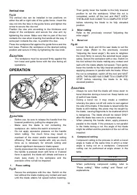
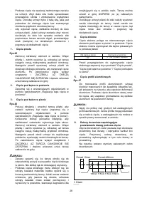
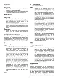
7. Cutting
repetitive
lengths
Fig.28
When cutting several pieces of stock to the same
length, ranging from 240 mm to 380 mm, use of the
set plate (optional accessory) will facilitate more
efficient operation. Install the set plate on the
holder (optional accessory) as shown in the figure.
Align the cutting line on your workpiece with either
the left or right side of the groove in the kerf board,
and while holding the workpiece from moving,
move the set plate flush against the end of the
workpiece. Then secure the set plate with the
screw. When the set plate is not used, loosen the
screw and turn the set plate out of the way.
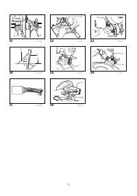
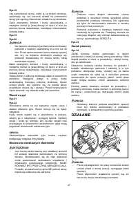
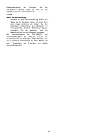
Carrying tool
Fig.29
Make sure that the tool is unplugged. Secure the blade
at 0° bevel angle and the turn base at left miter angle
fully. Lower the handle fully and lock it in the lowered
position by pushing in the stopper pin.
Carry the tool by carrying grip as shown in the figure. If
you remove the holders, dust bag, etc., you can carry
the tool more easily.
Fig.30
CAUTION:
•
Always secure all moving portions before carrying
the tool.
•
Stopper pin is for carrying and storage purposes
only and not for any cutting operations.
MAINTENANCE
CAUTION:
•
Always be sure that the tool is switched off and
unplugged before attempting to perform inspection
or maintenance.
•
Never use gasoline, benzine, thinner, alcohol or
the like. Discoloration, deformation or cracks may
result.
WARNING:
•
Always be sure that the blade is sharp and clean
for the best and safest performance.
Adjusting the cutting angle
This tool is carefully adjusted and aligned at the factory,
but rough handling may have affected the alignment. If
your tool is not aligned properly, perform the following:
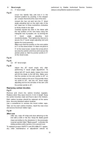
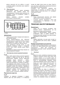
1. Miter
angle
Fig.31
Loosen the grip which secures the turn base. Turn
the turn base so that the pointer points to 0° on the
miter scale. Tighten the grip and loosen the hex
bolts securing the guide fence using the wrench. If
the pointer does not point to 0° on the miter scale,
loosen the screw which secures the pointer and
move and secure the pointer plate so that the
pointer points to 0° on the miter scale.
Lower the handle fully and lock it in the lowered
position by pushing in the stopper pin. Square the
side of the blade with the face of the guide fence
using a triangular rule, try-square, etc. Then
securely tighten the hex bolts on the guide fence in
the order from the right side.
Fig.32
1. Hole
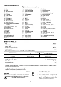
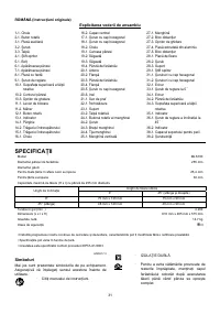
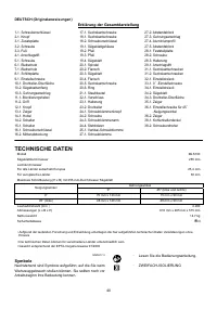
Характеристики

Остались вопросы?Не нашли свой ответ в руководстве или возникли другие проблемы? Задайте свой вопрос в форме ниже с подробным описанием вашей ситуации, чтобы другие люди и специалисты смогли дать на него ответ. Если вы знаете как решить проблему другого человека, пожалуйста, подскажите ему :)


