Котел Immergas Mini Eolo 24 3 E - инструкция пользователя по применению, эксплуатации и установке на русском языке. Мы надеемся, она поможет вам решить возникшие у вас вопросы при эксплуатации техники.
Если остались вопросы, задайте их в комментариях после инструкции.
"Загружаем инструкцию", означает, что нужно подождать пока файл загрузится и можно будет его читать онлайн. Некоторые инструкции очень большие и время их появления зависит от вашей скорости интернета.


30
STMiE3E ed 09/11
MINI EOLO 3 E
Technical Documentation
Technical Documentation
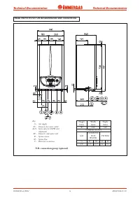
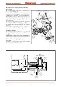
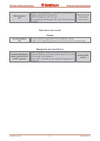
N.B.
with V.G. Honeywell
CONNECTION
FOR Virgilio
PALMTOP
CIRCUIT WITH VERY LOW
SAFETY VOLTAGE
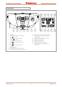
USER INTERFACE
LOGIC-CONT
ROLS MIC
ROP
ROCESSOR
D.H.W.
C.H.
Black
Brown
Blue
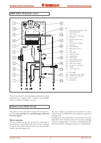
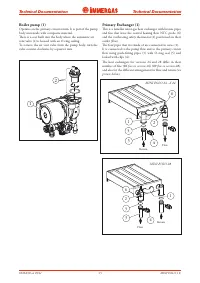
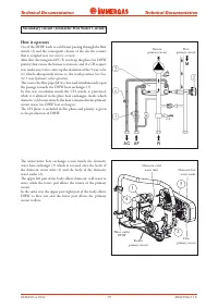
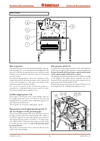
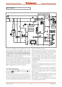
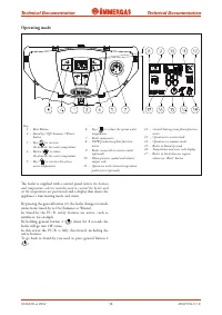
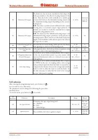
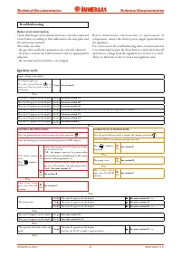
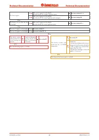
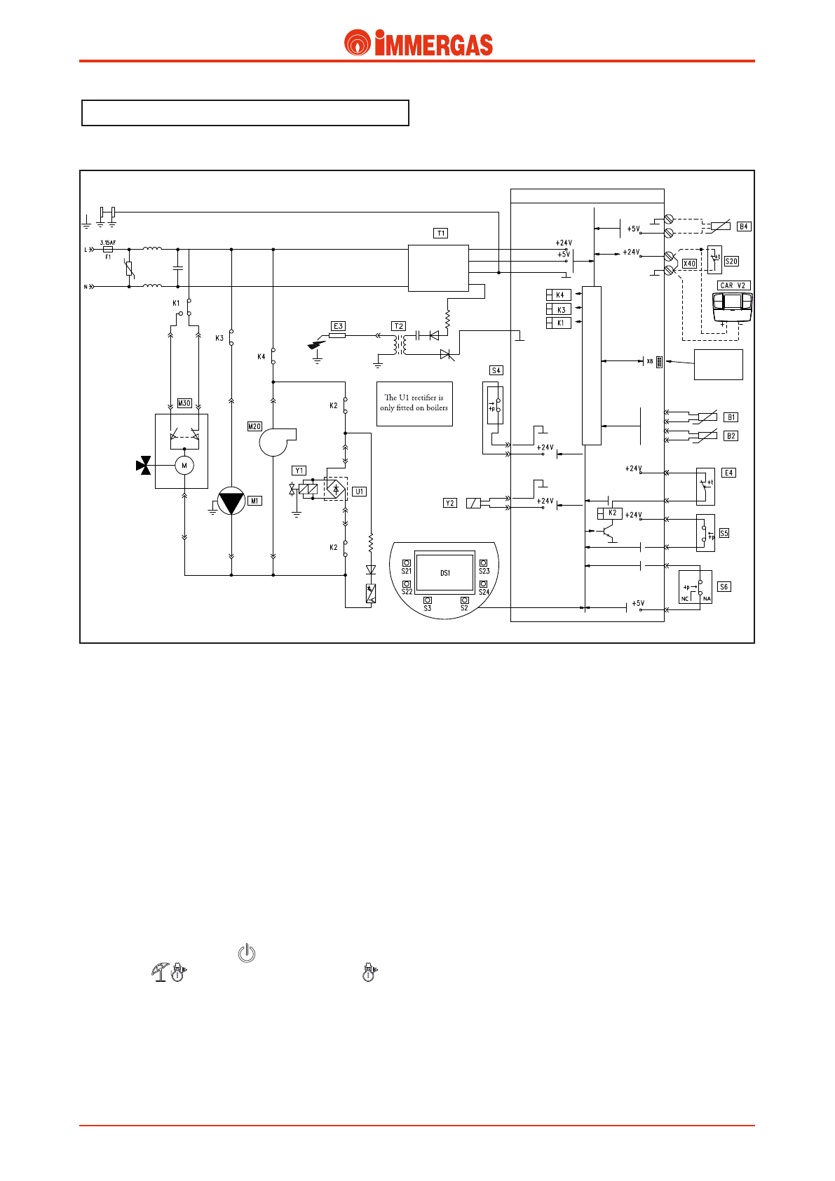
How it operates
The boiler is equipped with an integrated P.C.B. with
microprocessor for control of the appliance's electric devices,
which is designed for the linear modulation of burner output.
The board that is fitted on all models, whether they are
conventional flue or sealed chamber
(MINI NIKE/EOLO)
models,
the various boiler operating modes are detected
automatically via the appliance's wiring.
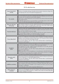
The P.C.B. carries out a periodical self-check to check it is
operating correctly. While operating in CH mode or with the
boiler in stand-by, the function goes on every 18 hours from
the last check/powering of the boiler. If operating in DHW
mode, the self-check starts within 10 minutes after the end
of the flow in progress for the duration of about 10 seconds.
N.B.:
during the self-check, the boiler remains off.
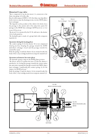
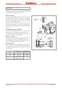
Central heating request
By pressing the main button (
) boiler activation is enabled.
By selecting (
) with the button, winter mode (
), the
CH mode is enabled.
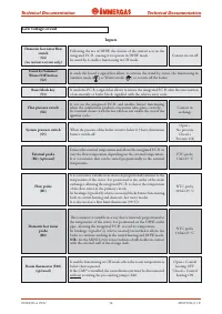
On closure of the room thermostat contact (S20), if the system
pressure switch contact (S5) is closed (pressure detected in the
primary circuit higher than minimum value),the integrated
P.C.B. powers the pump (M1) and the motor (M) of the 3-way
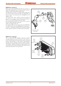
valve (M30). This functions until the end run switch "3" opens
when the CH position is reached.
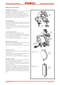
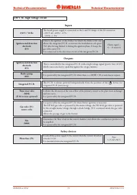
If the temperature detected by the NTC flow probe (B1) is
below the setting made on the boiler control panel with the
CH temperature selector and if the flue pressure switch contact
(S6) is at rest "NC", the P.C.B. powers the fan (M20).
With the subsequent deviation of the flue pressure switch
(S6) to "NA" and the consent of the safety thermostat (E4),
the integrated P.C.B. allows the ignition cycle to begin by
controlling the ignition electrode (E3) and then, both the coils
of the gas valve (Y1).
The ignition of the burner is detected by the ionisation
electrode (E3).
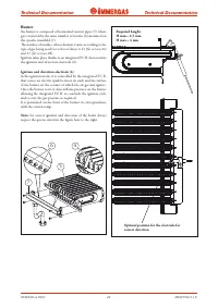
In the first seconds after the gas valve has been powered (Y1),
the current to the modulation coil (Y2) is limited to the pre-set
soft ignition current.
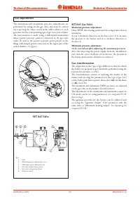
Following this the burner comes down to the minimum set
value ("Minimum CH output" parameter), to then reach, if
necessary, the maximum set value ("Maximum CH output"
parameter), in a defined amount of time, "CH ramp with
timer" parameter.
Successively, flame modulation takes place with reference to the
difference between the temperature set on the boiler control
panel and that detected by the DHW probe (B1).
On exceeding (+5°C) the temperature set, the burner is
switched off. The re-ignition time depends of the setting of
the "CH ignition timer" parameter.
Характеристики

Остались вопросы?Не нашли свой ответ в руководстве или возникли другие проблемы? Задайте свой вопрос в форме ниже с подробным описанием вашей ситуации, чтобы другие люди и специалисты смогли дать на него ответ. Если вы знаете как решить проблему другого человека, пожалуйста, подскажите ему :)


