Котел Immergas Mini Eolo 24 3 E - инструкция пользователя по применению, эксплуатации и установке на русском языке. Мы надеемся, она поможет вам решить возникшие у вас вопросы при эксплуатации техники.
Если остались вопросы, задайте их в комментариях после инструкции.
"Загружаем инструкцию", означает, что нужно подождать пока файл загрузится и можно будет его читать онлайн. Некоторые инструкции очень большие и время их появления зависит от вашей скорости интернета.


24
STMiE3E ed 09/11
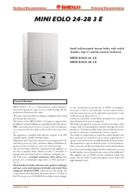
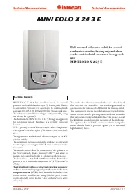
MINI EOLO 3 E
Technical Documentation
Technical Documentation
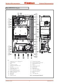
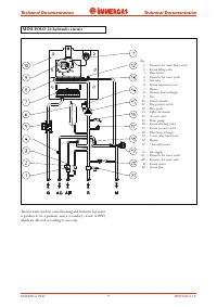
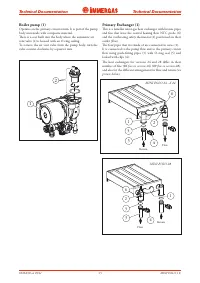
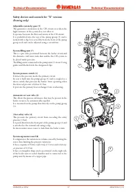
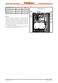
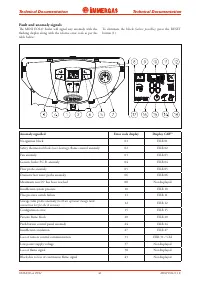
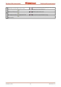
Flue circuit
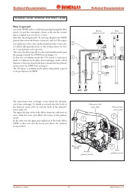
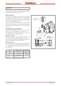
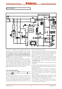
How it operates
The combustion products, after having reached the water-gas
heat exchanger (1), are slowed down and distributed by the
plate (12), with the consequential increase in combustion yield
and then sent to a hood (2) with a flue extractor (3) mounted
on top of it (fan).
Fan functioning guarantees the forced expulsion of the
combustion products and in the meantime creates a depression
in the sealed chamber (5). This allows the intake of the
combustion agent air from the outside.
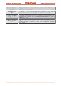
The correct evacuation of the combustion products is
controlled by a differential flue pressure switch (4) whose
intervention enables burner ignition or not.
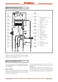
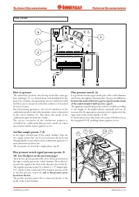
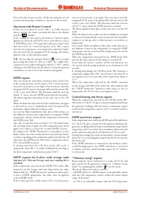
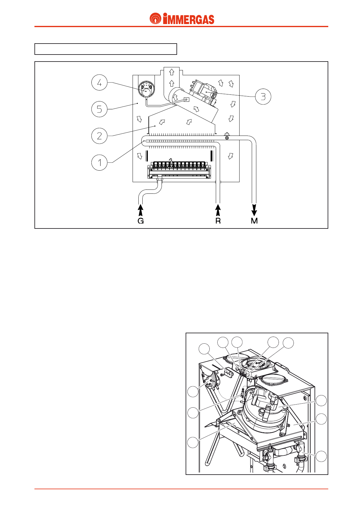
Air/flue sample points (7-8)
In the upper external part of the sealed chamber there are
two sample points that can be accessed from the front and
through which it is possible to draw combustion agent air (7)
and combustion products (8).
The two points are closed by a single plastic cap (6).
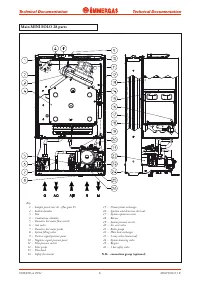
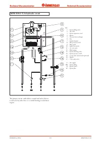
Flue pressure switch signal pressure points (9-
10)
(see the figure on the previous page)
There are two pressure points with screw closure positioned on
the upper outside part of the sealed chamber. These allow to
measure the signal at the ends of the flue pressure switch (4).
The negative pressure point (9) is fitted to a "Y"-shaped pipe
(11), which is then connected to the negative pressure point
of the flue pressure switch (4)
and to the pressure point
located on the fan.
The positive pressure point (10) is connected directly to the
inside of the sealed chamber.
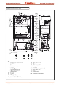
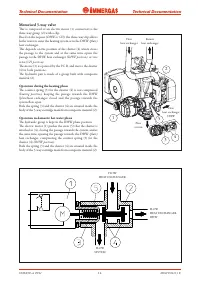
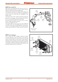
Flue pressure switch (4)
It is positioned in the upper inside part of the sealed chamber
and detects,through the relevant points, the pressure difference
between the inside of the fan
(negative signal)
and the inside
of the sealed chamber itself
(positive signal)
.
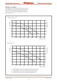
The signal measured by the pressure switch is variable according
to the length of the intake/exhaust terminals and can be
measured by the appropriate pressure points organised in the
upper part of the sealed chamber (9-10).
Its intervention causes the closure of a contact (S6) that acts on
the integrated P.C.B. enabling burner ignition or not.
2
1
3
4
7 8
9
10
6
11
12
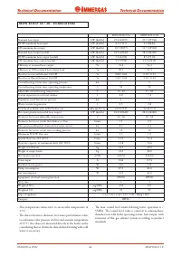
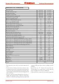
Характеристики

Остались вопросы?Не нашли свой ответ в руководстве или возникли другие проблемы? Задайте свой вопрос в форме ниже с подробным описанием вашей ситуации, чтобы другие люди и специалисты смогли дать на него ответ. Если вы знаете как решить проблему другого человека, пожалуйста, подскажите ему :)


