Котел Immergas Mini Eolo 24 3 E - инструкция пользователя по применению, эксплуатации и установке на русском языке. Мы надеемся, она поможет вам решить возникшие у вас вопросы при эксплуатации техники.
Если остались вопросы, задайте их в комментариях после инструкции.
"Загружаем инструкцию", означает, что нужно подождать пока файл загрузится и можно будет его читать онлайн. Некоторые инструкции очень большие и время их появления зависит от вашей скорости интернета.


27
STMiE3E ed 09/11
MINI EOLO 3 E
Technical Documentation
Technical Documentation
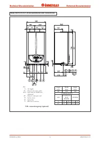
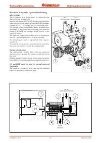
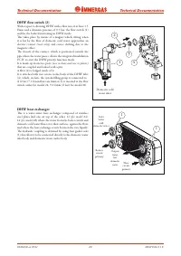
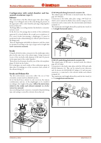
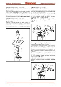
Ø 60/100 push-fitting horizontal concentric kit
The exhaust pipe (Ø 60 mm) is inserted inside the exhaust
pipe (Ø 100 mm).
Connection to the boiler takes place using a 90º bend (2),
which can be turned in all directions and by using necessary
extensions can be connected to the relevant intake and exhaust
terminal (3).
The maximum total length allowed beyond the first bend (2)
is
3 straight horizontal metres.
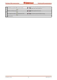
Ø 80/125 push-fitting horizontal concentric kit
The exhaust pipe (Ø 80 mm) is inserted inside the exhaust
pipe (Ø 125 mm).
Connection to the boiler takes place with the 90º bend with
60/100 diameter (2). This can be turned in any direction
and, by means of a 60/100-80/125 adapter (3) and necessary
extensions, is connected to the relevant intake and exhaust
terminal (4).
The maximum total length allowed beyond the first bend (2)
is
7.3 straight horizontal metres.
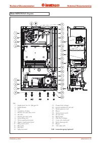
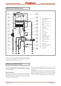
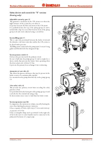
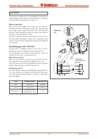
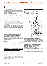
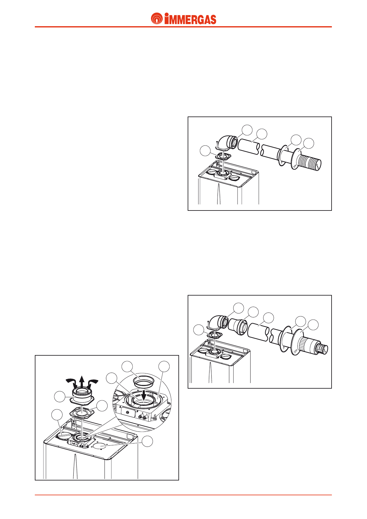
Configuration with sealed chamber and fan-
assisted circulation (type C)
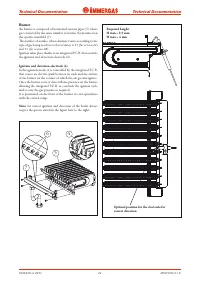
Exhaust
The connection to the flue exhaust pipes takes place using a
flange (1) or a flanged curve to fix to the fitting (4) present on
the upper part of the sealed chamber, placing a shaped gasket
between them (6).
The flange differs according whether the divided or concentric
system is used.
In the first case the passage due to intake of the combustion
agent air (5) is closed while in the second case it is made use of.
For correct boiler functioning, a diaphragm (7) must be
positioned on the exhaust fitting (4), which is placed between
the flange used.
There are diaphragms with different diameters and these must
be mounted according to the type of pipe and its length
(see
boiler instruction manual).
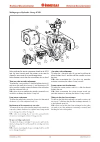
Intake
Using the divided system, connection to the intake pipes takes
place in the same way as the exhaust pipes, being connected
to one of the two holes with diameter of 80 mm (2) present
in the upper part of the sealed chamber.
The hole not used remains closed by one of the relevant plastic
plugs (3) fitted on the boilers.
If co-axial pipes are used, intake of the combustion agent air
takes place by making use of the concentric hole outside of
the exhaust fitting (5).
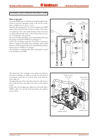
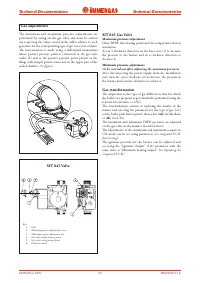
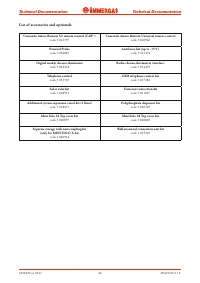
Intake and Exhaust Kit
The kits with relative accessories allow the use of four
concentric systems and two divided systems.
As for the head losses related to each accessory, the various
combinations and use of the diaphragms to be installed
according to the length of the pipes,
follow the instructions
related to the intake and exhaust terminals
(see boiler
instruction manual).
Accessory fitting (bends, extensions, terminals) is the push-fitting
type and sealing is assured by relevant silicon lip seals.
1
3
2
5 6
4
1
3
2
4 5
1
2
3
4
5
7
6
Характеристики

Остались вопросы?Не нашли свой ответ в руководстве или возникли другие проблемы? Задайте свой вопрос в форме ниже с подробным описанием вашей ситуации, чтобы другие люди и специалисты смогли дать на него ответ. Если вы знаете как решить проблему другого человека, пожалуйста, подскажите ему :)


