Котел Ferroli DIVAtop MICRO F WF - инструкция пользователя по применению, эксплуатации и установке на русском языке. Мы надеемся, она поможет вам решить возникшие у вас вопросы при эксплуатации техники.
Если остались вопросы, задайте их в комментариях после инструкции.
"Загружаем инструкцию", означает, что нужно подождать пока файл загрузится и можно будет его читать онлайн. Некоторые инструкции очень большие и время их появления зависит от вашей скорости интернета.
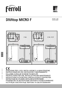
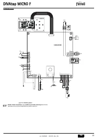


DIVAtop MICRO F
41
EN
cod. 3540S261 - 02/2010 (Rev. 00)
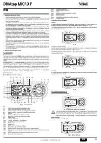
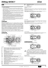
Checks during operation
•
Ignite the appliance as described in sec. 2.3.
•
Check the airtightness of the fuel circuit and water systems.
•
Check the efficiency of the flue and air-fume ducts while the boiler is working.
•
Check that the water is circulating properly between the boiler and the systems.
•
Make sure that the gas valve modulates correctly in both the heating and hot water
production phases.
•
Check the proper ignition of the boiler by performing various tests, turning it on and
off with the room thermostat or remote control.
•
Make sure that the fuel consumption indicated on the meter corresponds to that giv-
en in the technical data table in sec. 5.2.
•
Make sure that with no call for heating the burner correctly ignites on opening a hot
water tap. Check that during heating operation, on opening a hot water tap, the heat-
ing circulator stops and there is a regular production of hot water.
•
Check the parameters are programmed correctly and perform any required custom-
ization (compensation curve, power, temperatures, etc.)
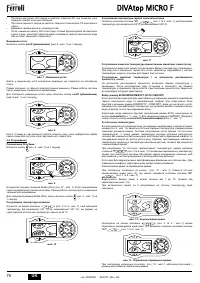
4.3 Maintenance
Periodical check
To ensure proper operation of the unit over time, have qualified personnel carry out a
yearly check, providing for the following:
•
The control and safety devices (gas valve, flowmeter, thermostats, etc.) must func-
tion correctly.
•
The fume exhaust circuit must be perfectly efficient.
(Sealed chamber boiler: fan, pressure switch, etc. - The sealed chamber must be
tight: seals, cable glands, etc.)
(Open chamber boiler: anti-backflow device, fume thermostat, etc.)
•
The air/fume terminal and ducts must be free of obstructions and leaks
•
The burner and exchanger must be clean and free of deposits. For cleaning do not
use chemical products or wire brushes.
•
The electrode must be free of scale and properly positioned.
•
The gas and water systems must be tight.
•
The water pressure in the cold water system must be approx. 1 bar; otherwise bring
it to that value.
•
The circulating pump must not be blocked.
•
The expansion tank must be filled.
•
The gas flowrate and pressure must match that given in the respective tables.
A
The boiler casing, control panel and aesthetic parts can be cleaned with a soft
damp cloth, if necessary soaked in soapy water. Do not use any abrasive de-
tergents and solvents.
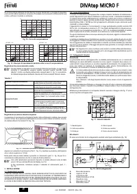
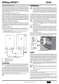
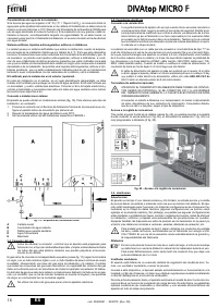
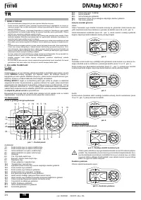
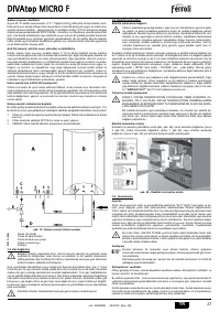
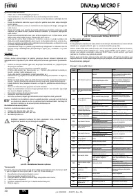
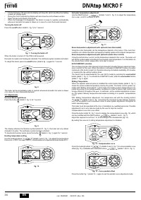
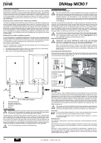
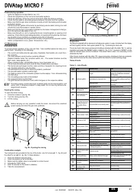
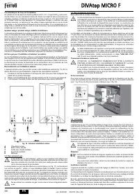
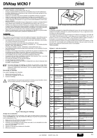
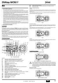
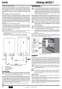
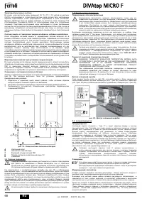
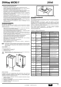
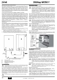
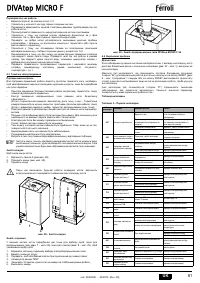
Opening the casing
To open the boiler casing:
1.
Undo the screws A (see fig. 28).
2.
Turn the casing (see fig. 28).
3.
Lift the casing.
B
Before carrying out any operation inside the boiler, disconnect the electrical
power supply and close the gas cock upstream
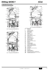
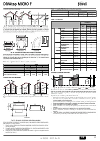
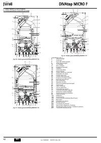
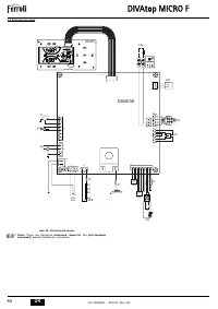
fig. 28 - Opening the casing
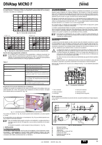
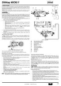
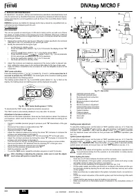
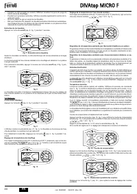
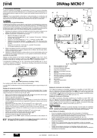
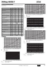
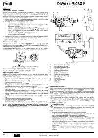
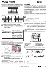
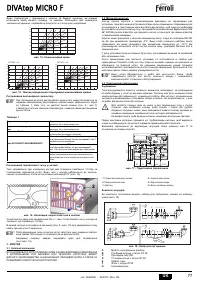
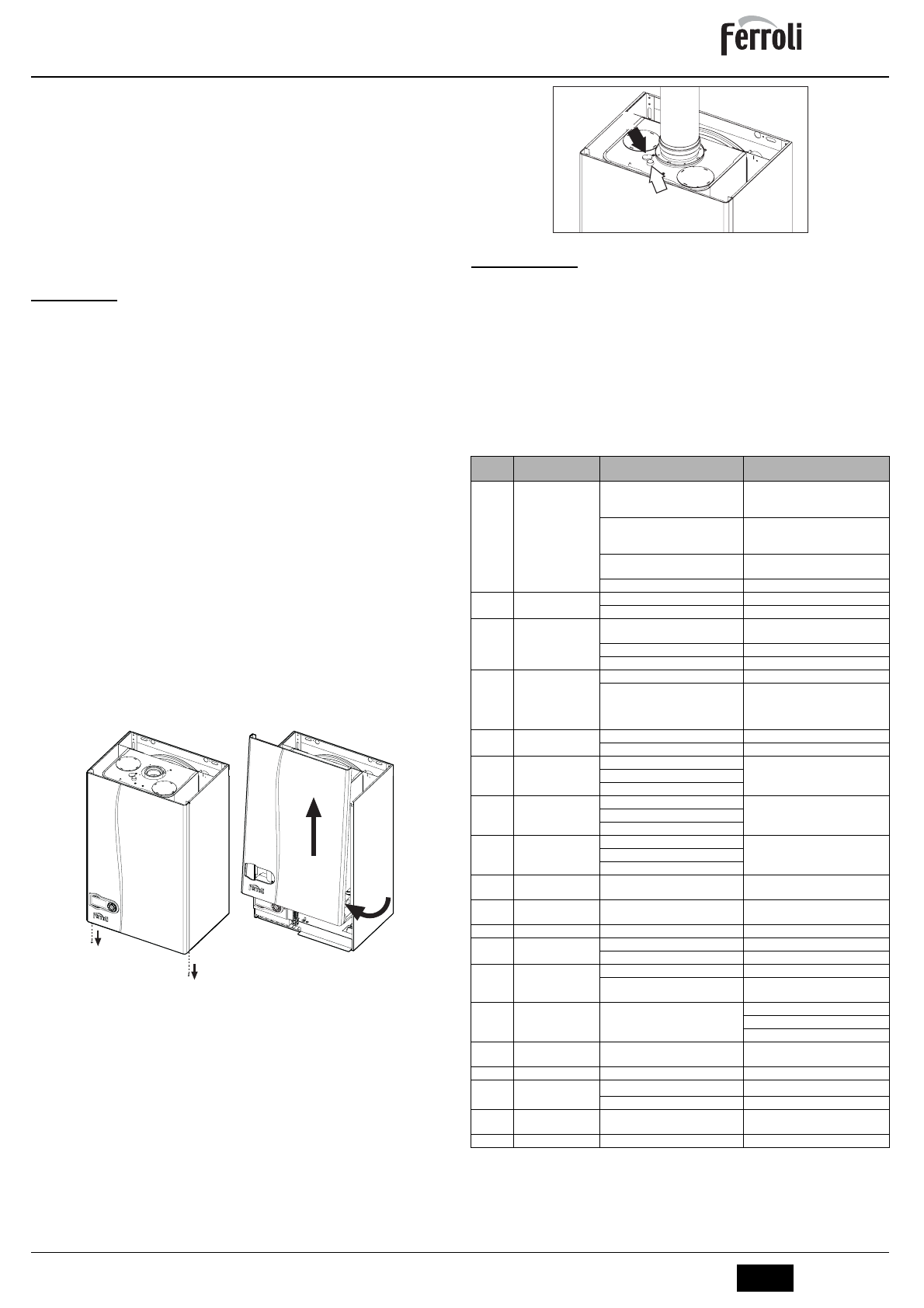
Combustion analysis
Two test points are provided at the top of the boiler, one for fumes (
ref. 1
- fig. 29) and
the other for air (
ref. 2
- fig. 29). To take samples:
1.
Open the air/fume test point plug;
2.
Insert the probes as far as the stop;
3.
Make sure the safety valve is connected to a drain funnel;
4.
Activate the TEST mode;
5.
Wait 10 minutes for the boiler to stabilise;
6.
Take the measurement.
fig. 29 - Fume analysis DIVAtop MICRO F 24
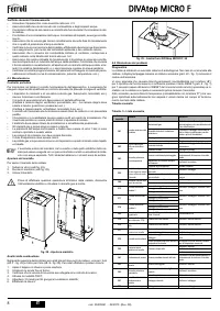
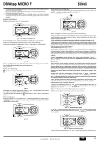
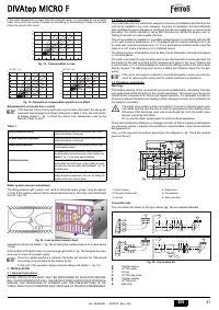
4.4 Troubleshooting
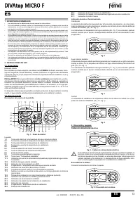
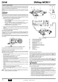
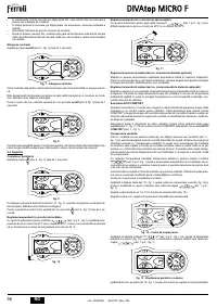
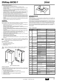
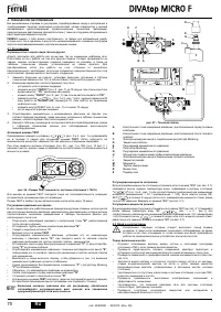
Diagnostics
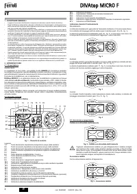
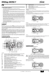
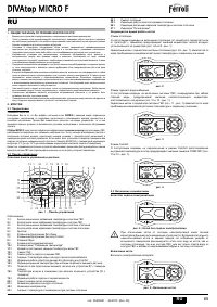
The boiler is equipped with an advanced self-diagnosis system. In case of a boiler fault, the display
will flash together with the fault symbol (detail 22 - fig. 1) indicating the fault code.
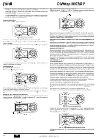
There are faults that cause permanent shutdown (marked with the letter “
A
”): to restore
operation just press the RESET button (detail 8 - fig. 1) for 1 second or RESET on the
optional remote timer control if installed; if the boiler fails to start, it is necessary to first
eliminate the fault.
Other faults (marked with the letter “
F
”) cause temporary shutdowns that are automati-
cally reset as soon as the value returns within the boiler's normal working range.
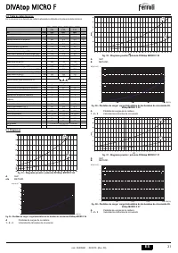
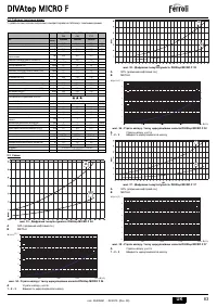
Table of faults
Table. 5 - List of faults
A
A
1
3
2
Fault
code
Fault
Possible cause
Cure
A01
No burner ignition
No gas
Check the regular gas flow to the boiler
and that the air has been eliminated
from the pipes
Ignition/detection electrode fault
Check the wiring of the electrode and
that it is correctly positioned and free of
any deposits
Faulty gas valve
Check the gas valve and replace it if
necessary
Ignition power too low
Adjust the ignition power
A02
Flame present signal
with burner off
Electrode fault
Check the ionisation electrode wiring
Card fault
Check the card
A03
Overtemperature pro-
tection activation
Heating sensor damaged
Check the correct positioning and oper-
ation of the heating sensor
No water circulation in the system
Check the circulating pump
Air in the system
Vent the system
F05
The air pressure trans-
ducer does not receive
a sufficient minimum
value within 25 sec-
onds
Incorrect air pressure transducer wiring Check the wiring
Flue obstructed or not correctly sized
Check the length of flue and that it is
clean
A06
No flame after ignition
phase
Low pressure in gas system
Check the gas pressure
Burner minimum pressure setting
Check the pressures
F10
Delivery sensor 1 fault
Sensor damaged
Check the wiring or replace the sensor
Wiring shorted
Wiring disconnected
F11
DHW sensor fault
Sensor damaged
Check the wiring or replace the sensor
Wiring shorted
Wiring disconnected
F14
Delivery sensor 2 fault
Sensor damaged
Check the wiring or replace the sensor
Wiring shorted
Wiring disconnected
A15
Air signal protection
activation
Fault F05 generated 5 times in the last
15 minutes
See fault F05
F34
Supply voltage under
170V.
Electric mains trouble
Check the electrical system
F35
Faulty mains frequency Electric mains trouble
Check the electrical system
F37
Incorrect system water
pressure
Pressure too low
Fill the system
Sensor damaged
Check the sensor
F39
External probe fault
Probe damaged or wiring shorted
Check the wiring or replace the sensor
Sensor disconnected after activating
the sliding temperature
Reconnect the external probe or disable
the sliding temperature
F40
Incorrect system water
pressure
Pressure too high
Check the system
Check the safety valve
Check the expansion tank
A41
Sensor positioning
Delivery sensor detached from pipe
Check the correct positioning and oper-
ation of the heating sensor
F42
Heating sensor fault
Sensor damaged
Replace the sensor
F43
Exchanger protection
activation.
No system H
2
O circulation
Check the circulating pump
Air in the system
Vent the system
F47
System water pres-
sure sensor fault
Wiring disconnected
Check the wiring
F50
Modureg fault
Wiring disconnected
Check the wiring
1
2

