Котел Ferroli DIVAtop MICRO F WF - инструкция пользователя по применению, эксплуатации и установке на русском языке. Мы надеемся, она поможет вам решить возникшие у вас вопросы при эксплуатации техники.
Если остались вопросы, задайте их в комментариях после инструкции.
"Загружаем инструкцию", означает, что нужно подождать пока файл загрузится и можно будет его читать онлайн. Некоторые инструкции очень большие и время их появления зависит от вашей скорости интернета.
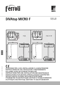
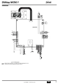

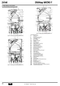
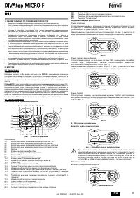


DIVAtop MICRO F
39
EN
cod. 3540S261 - 02/2010 (Rev. 00)
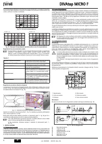
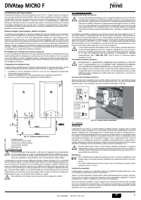
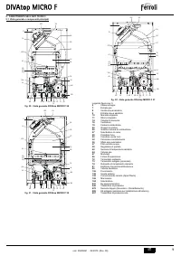
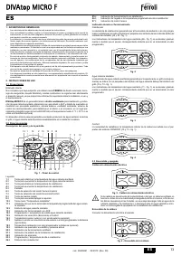
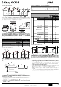
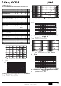
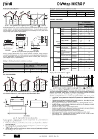
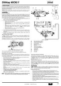
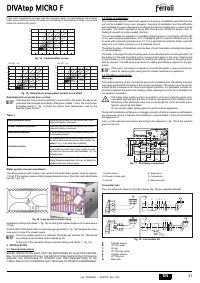
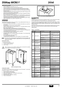
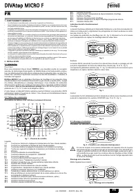
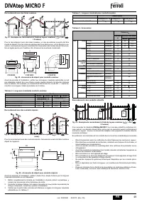
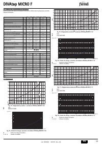
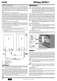
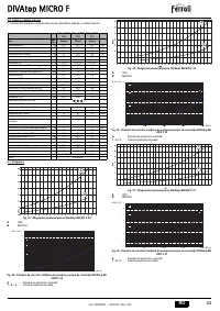
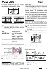
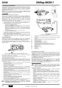
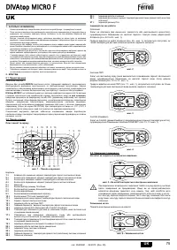
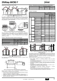
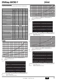
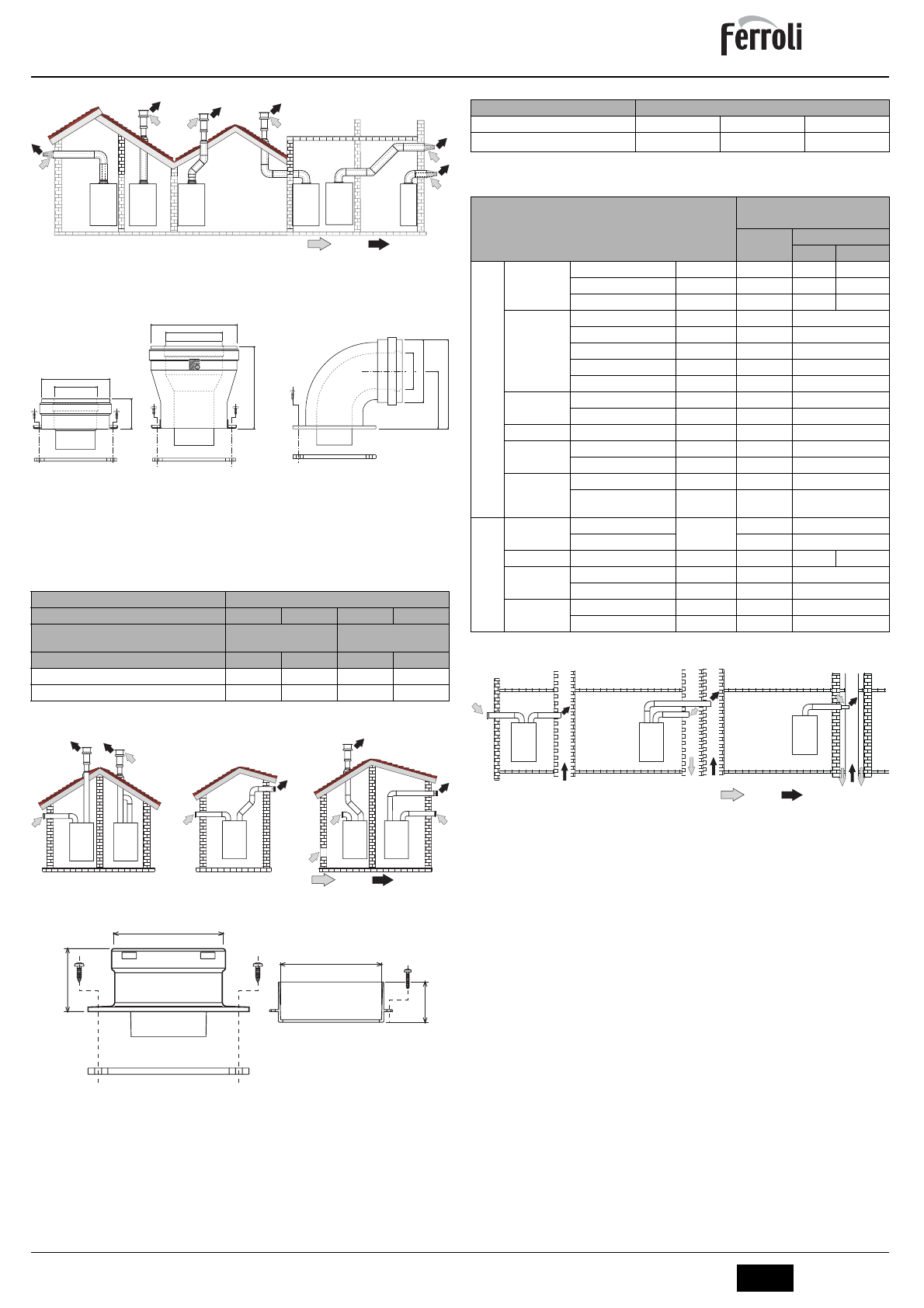
Connection with coaxial pipes
fig. 21 - Examples of connection with coaxial pipes (
= Air /
= Fumes)
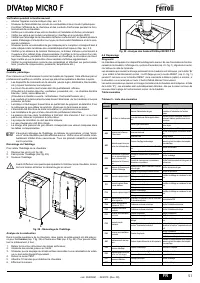
For coaxial connection, fit the unit with one of the following starting accessories. For the
wall hole dimensions, refer to the figure on the cover. Any horizontal sections of the fume
exhaust must be kept sloping slightly towards the outside, to prevent condensate from
flowing back towards the unit.
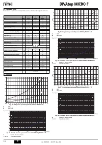
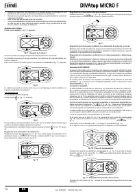
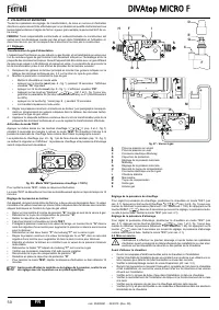
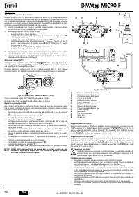
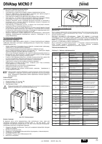
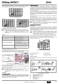
fig. 22 - Starting accessories for coaxial ducts
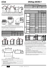
Before proceeding with installation, check that the maximum permissible length is not
exceeded, bearing in mind that everycoaxial bend gives rise to the reduction indicated in
the table. For example, a Ø 60/100 duct comprising a 90° bend + 1 horizontal metre has
a total equivalent length of 2 metres.
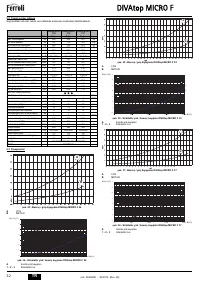
Table. 2 - Max. length coaxial ducts
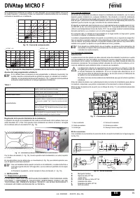
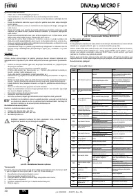
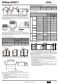
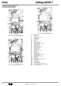
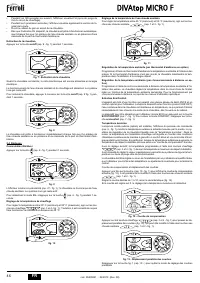
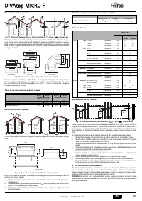
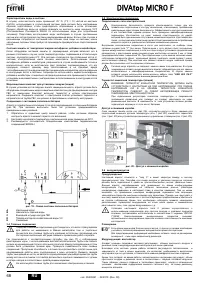
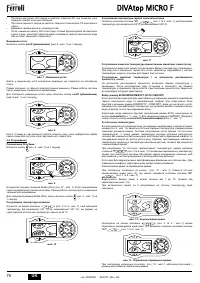
Connection with separate pipes
fig. 23 - Examples of connection with separate pipes (
= Air /
= Fumes)
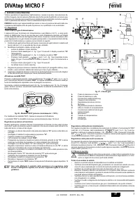
For connection of the separate ducts, fit the unit with the following starting accessory:
fig. 24 - Starting accessory for separate ducts
Before proceeding with installation make sure the maximum permissible length has not
been exceeded, by means of a simple calculation:
1.
Completely establish the layout of the system of split flues, including accessories
and outlet terminals.
2.
Consult the table 4 and identify the losses in m
eq
(equivalent metres) of every com-
ponent, according to the installation position.
3.
Check that the sum total of losses is less than or equal to the maximum permissible
length in table 3.
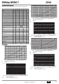
Table. 3 - Max. length for separate ducts
Table. 4 - Accessories
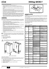
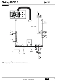
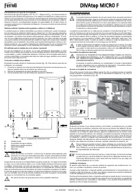
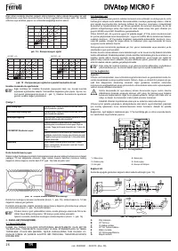
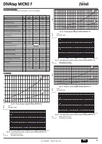
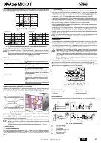
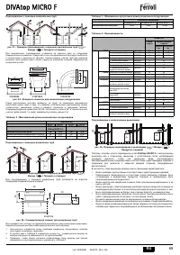
Connection to multiple flues
fig. 25 - Examples of connection to flues (
= Air /
= Fumes)
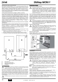
To connect the boiler
DIVAtop MICRO F
to a multiple flue or a single chimney with nat-
ural draught, the flue or chimney must be expressly designed by professionally qualified
technical personnel in conformity with the current regulations and be suitable for sealed
chamber units equipped with a fan.
In particular, chimneys and flues must have the following characteristics:
•
Be sized according to the method of calculation given in the current regulations.
•
Be fumetight, resistant to the fumes and heat and impermeable to condensate.
•
Have a round or square section, with vertical run and without constrictions.
•
Have the ducts conveying the hot fumes, adequately separated or isolated from
combustible materials.
•
Be connected to only one unit per floor.
•
Be connected to a single type of unit (or all and only forced draught units or all and
only natural draught units).
•
Have no mechanical suction devices in the main ducts.
•
Be at low pressure, along the entire length, under conditions of stationary operation.
•
Have a collection chamber at their base for solid materials or possible condensate,
equipped with an airtight metal door.
Coaxial
60/100
80/125
60/100
80/125
DIVAtop MICRO F 24
DIVAtop MICRO F 32
DIVAtop MICRO F 37
Max. permissible length
5 m
10 m
4 m
10 m
Reduction factor 90° bend
1 m
0.5 m
1 m
0.5 m
Reduction factor 45° bend
0.5 m
0.25 m
0.5 m
0.25 m
C
12
C
12
C
32
C
32
C
32
C
12
010014X0
010006X0
010007X0
80
100
60
125
68
11
8
123.5
45.6
100
60
C
52
C
32
C
52
B
22
C
12
50
80
010011X0
80
32
Separate ducts
DIVAtop MICRO F 24 DIVAtop MICRO F 32 DIVAtop MICRO F 37
Max. permissible length
60 m
eq
48 m
eq
40 m
eq
Losses in m
eq
Air
inlet
Fume exhaust
Vertical
Horizontal
Ø 80
PIPE
0.5 m M/F
1KWMA38A
0.5
0.5
1.0
1 m M/F
1KWMA83A
1.0
1.0
2.0
2 m M/F
1KWMA06K
2.0
2.0
4.0
BEND
45° F/F
1KWMA01K
1.2
2.2
45° M/F
1KWMA65A
1.2
2.2
90° F/F
1KWMA02K
2.0
3.0
90° M/F
1KWMA82A
1.5
2.5
90° M/F + Test point
1KWMA70U
1.5
2.5
PIPE SECTION
with test point
1KWMA16U
0.2
0.2
for condensate drain
1KWMA55U
-
3.0
TEE
for condensate drain
1KWMA05K
-
7.0
TERMINAL
air, wall
1KWMA85A
2.0
-
fumes, wall with antiwind
1KWMA86A
-
5.0
FLUE
Split air/fumes 80/80
1KWMA84U
-
12.0
Fume outlet only Ø80
1KWMA83U +
1KWMA86U
-
4.0
Ø 100
REDUCTION
from Ø80 to Ø100
1KWMA03U
0.0
0.0
from Ø100 to Ø80
1.5
3.0
PIPE
1 m M/F
1KWMA08K
0.4
0.4
0.8
BEND
45° M/F
1KWMA03K
0.6
1.0
90° M/F
1KWMA04K
0.8
1.3
TERMINAL
air, wall
1KWMA14K
1.5
-
fumes, wall with antiwind
1KWMA29K
-
3.0
C
82
C
42
C
42

