Котел Ferroli DIVAtop MICRO F WF - инструкция пользователя по применению, эксплуатации и установке на русском языке. Мы надеемся, она поможет вам решить возникшие у вас вопросы при эксплуатации техники.
Если остались вопросы, задайте их в комментариях после инструкции.
"Загружаем инструкцию", означает, что нужно подождать пока файл загрузится и можно будет его читать онлайн. Некоторые инструкции очень большие и время их появления зависит от вашей скорости интернета.
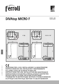


DIVAtop MICRO F
37
EN
cod. 3540S261 - 02/2010 (Rev. 00)
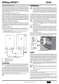
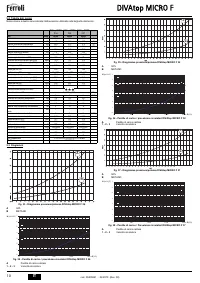
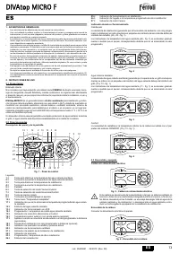
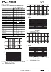
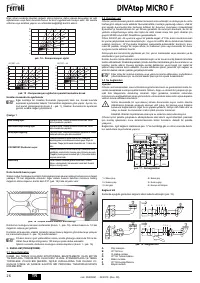
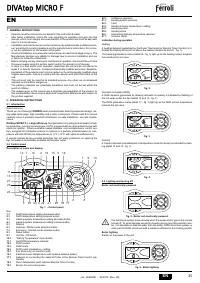
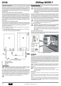
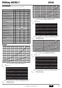
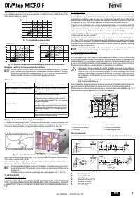
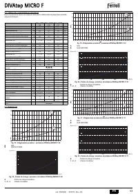
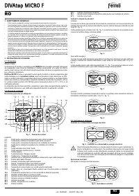
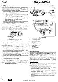
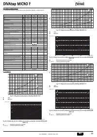
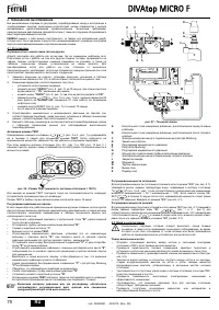
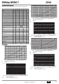
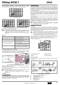
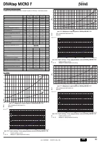
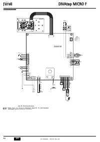
If the room temperature is lower than the required value, it is advisable to set a higher
order curve and vice versa. Proceed by increasing or decreasing in steps of one and
check the result in the room.
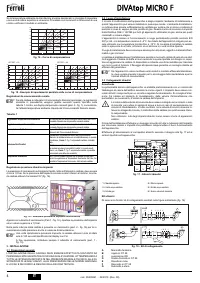
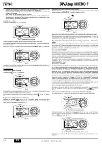
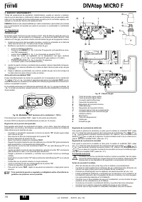
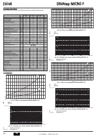
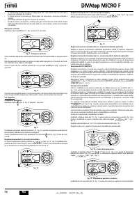
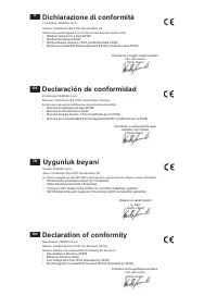
fig. 14 - Compensation curves
fig. 15 - Example of compensation parallel curve offset
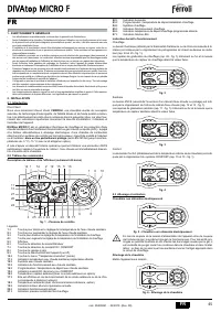
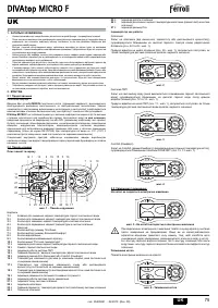
Adjustments from remote timer control
A
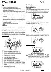
If the Remote Timer Control (optional) is connected to the boiler, the above ad-
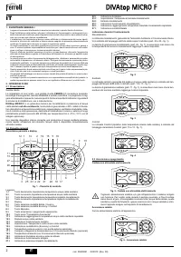
justments are managed according to that given in table 1. Also, the control pan-
el display (detail 5 - fig. 1) shows the actual room temperature read by the
Remote Timer Control.
Table. 1
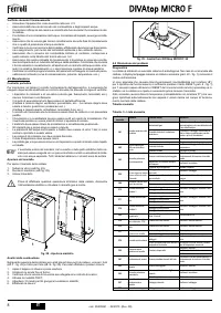
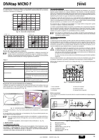
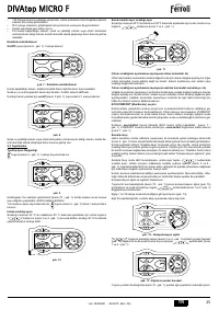
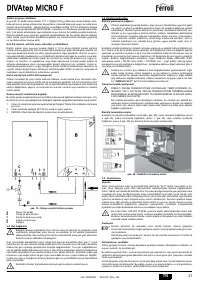
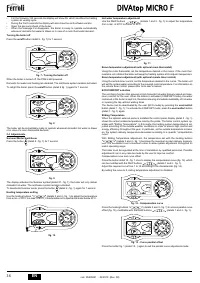
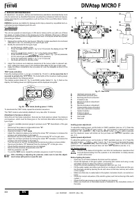
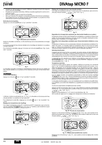
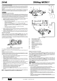
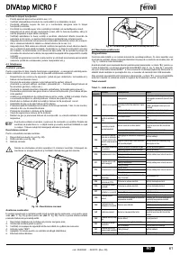
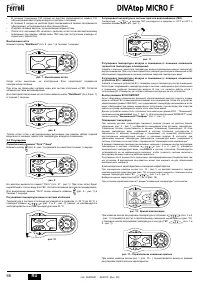
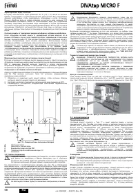
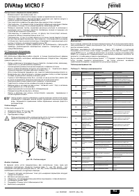
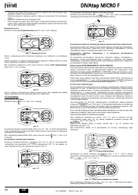
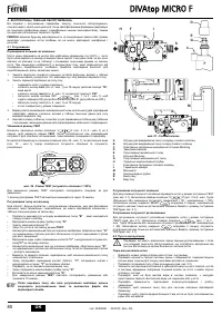
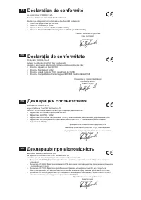
Water system pressure adjustment
The filling pressure with system cold, read on the boiler water gauge, must be approx.
1.0 bar. If the system pressure falls to values below minimum, the boiler card will activate
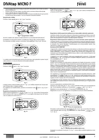
fault F37 (fig. 16).
fig. 16 - Low system pressure fault
Operate the filling cock (detail 1 - fig. 16) and bring the system pressure to a value above
1.0 bar.
At the bottom of the boiler there is a pressure gauge (detail 2 - fig. 16) that gives the pres-
sure even in case of no power supply.
A
Once the system pressure is restored, the boiler will activate the 120-second
air venting cycle indicated on the display by FH.
At the end of the operation always close the filling cock (detail 1 - fig. 16)
3. INSTALLATION
3.1 General Instructions
BOILER INSTALLATION MUST ONLY BE PERFORMED BY QUALIFIED PERSON-
NEL, IN ACCORDANCE WITH ALL THE INSTRUCTIONS GIVEN IN THIS TECHNICAL
MANUAL, THE PROVISIONS OF CURRENT LAW, THE PRESCRIPTIONS OF NA-
TIONAL AND LOCAL STANDARDS AND THE RULES OF PROPER WORKMANSHIP.
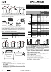
3.2 Place of installation
The combustion circuit is sealed with respect to the place of installation and therefore the
unit can be installed in any room. However, the place of installation must be sufficiently
well ventilated to prevent dangerous conditions from being created even in case of small
gas leaks. This safety standard is set by EEC Directive no. 90/396 for all gas units, in-
cluding those with so-called sealed chamber.
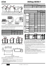
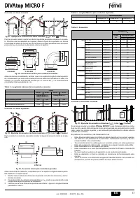
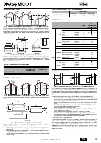
The unit is suitable for operation in a partially protected place in conformity with EN 297
pr A6, with minimum temperature -5°C. If equipped with the special antifreeze kit it can
be used with minimum temperature to -15°C. It is advisable to install the boiler under the
slope of a roof, inside a balcony or in a sheltered recess.
Therefore the place of installation must be free of dust, flammable materials and objects
or corrosive gases.
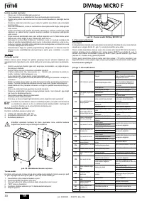
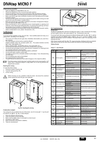
The boiler is arranged for wall mounting and comes standard with a hooking bracket. Fix
the bracket to the wall according to the measurements given in the cover drawing and
hook the boiler on it. A metal template for marking the drilling points on the wall is avail-
able by request. The wall fixing must ensure a stable and effective support for the gen-
erator.
A
If the unit is enclosed in a cabinet or mounted alongside, a space must be pro-
vided for removing the casing and for normal maintenance operations.
3.3 Plumbing connections
Warnings
The heating capacity of the unit must be previously established by calculating the build-
ing's heat requirement according to the current regulations. The system must be provid-
ed with all the components for correct and regular operation. It is advisable to install on-
off valves between the boiler and heating system allowing the boiler to be isolated from
the system if necessary.
B
The safety valve outlet must be connected to a funnel or collection pipe to pre-
vent water spurting onto the floor in case of overpressure in the heating circuit.
Otherwise, if the discharge valve cuts in and floods the room, the boiler manu-
facturer cannot be held liable.
Do not use the water system pipes to earth electrical appliances.
Prima dell'installazione effettuare un lavaggio accurato di tutte le tubazioni dell'impianto
per rimuovere residui o impurità che potrebbero compromettere il buon funzionamento
dell'apparecchio.
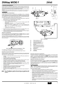
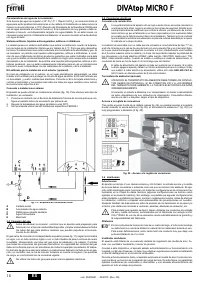
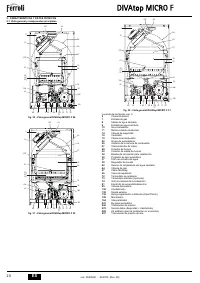
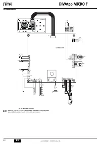
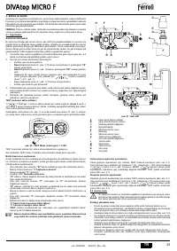
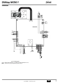
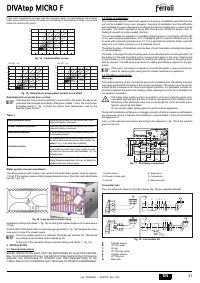
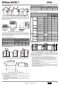
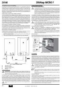
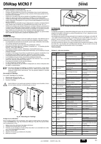
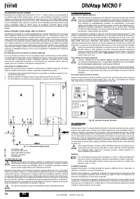
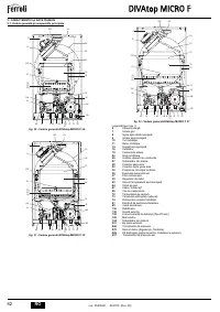
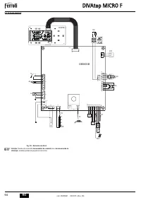
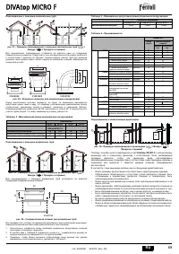
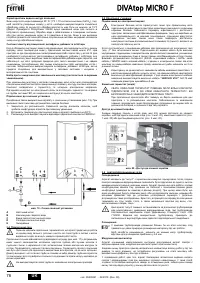
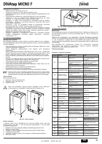
Carry out the relevant connections according to the diagram in fig. 17and the symbols
given on the unit.
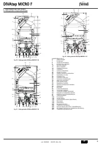
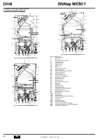
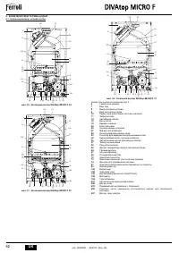
fig. 17 - Plumbing connections
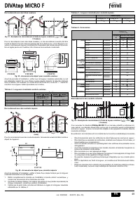
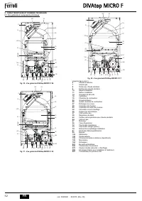
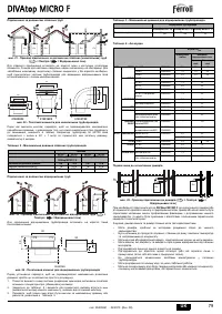
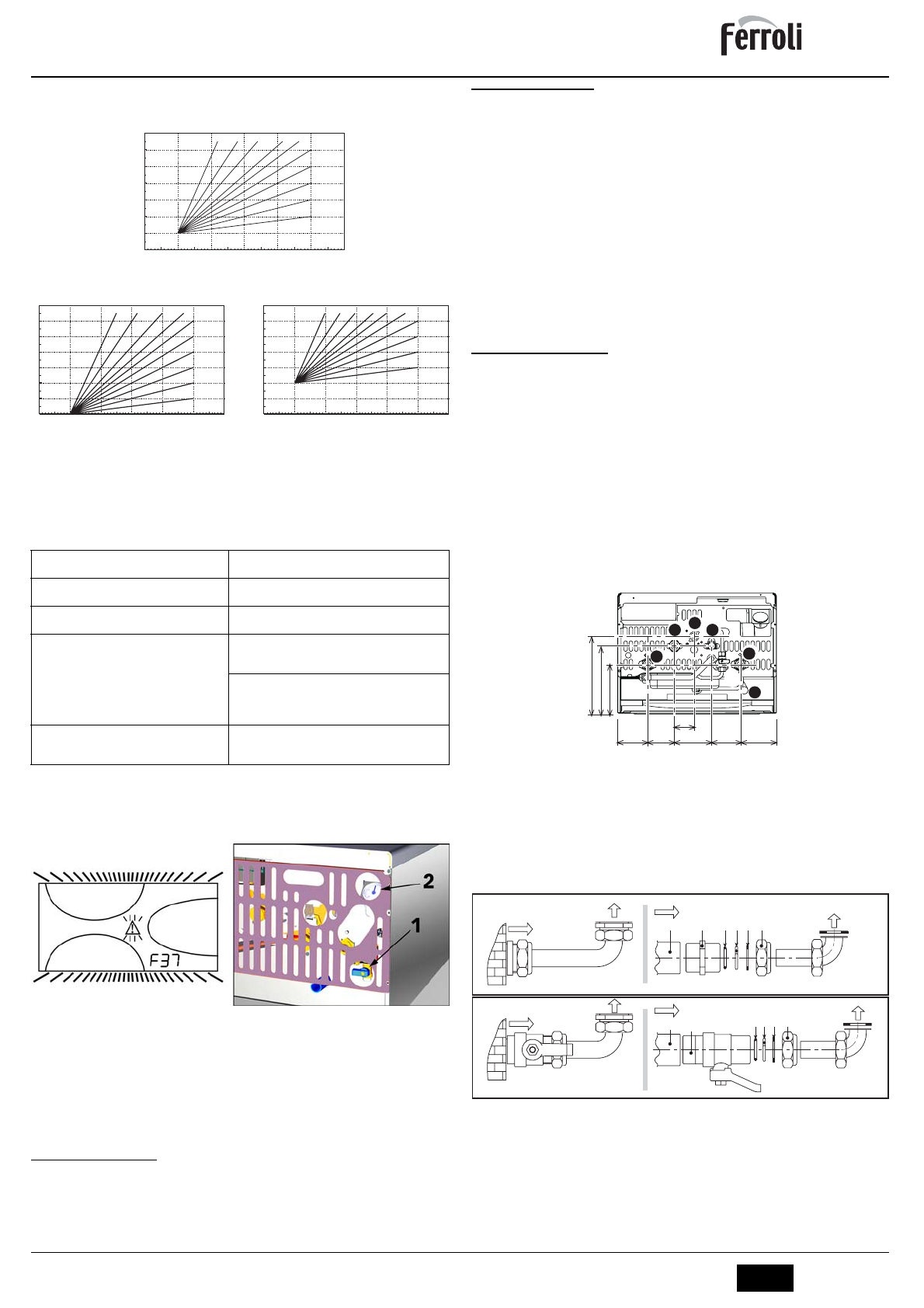
Connection kits
The connection kits shown in the figure below (fig. 18) are supplied standard
fig. 18 - Connection kit
A
Female sleeve
B
OT 58 nipple
C
O-ring
D
OT 58 stop collar
E
Copper washer
F
OT 58 union
G
Ball cock
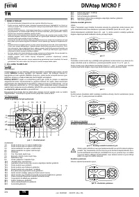
Heating temperature setting
Adjustment can be made from the Remote Timer Control
menu and the boiler control panel.
Hot water temperature adjustment
Adjustment can be made from the Remote Timer Control
menu and the boiler control panel.
Summer/Winter Switchover
Summer mode has priority over a possible Remote Timer
Control heating demand.
Eco/Comfort selection
On disabling DHW from the Remote Timer Control menu,
the boiler selects the Economy mode. In this condition, the
button 7
- fig. 1 on the boiler panel is disabled.
On enabling DHW from the Remote Timer Control menu, the
boiler selects the Comfort mode. In this condition it is possi-
ble select one of the two modes with the
button 7
- fig. 1 on
the boiler panel.
Sliding Temperature
Both the Remote Timer Control and the boiler card manage
Sliding Temperature adjustment: of the two, the Sliding Tem-
perature of the boiler card has priority.
20
30
40
50
60
70
80
90
85
20
10
0
-10
-20
1
2
3
4
5
6
8
9
10
7
20
30
40
50
60
70
80
90
85
20
10
0
-10
-20
1
2
3
4
5
6
8
9
10
7
20
10
0
-10
-20
20
30
40
50
60
70
80
90
85
1
2
3
4
5
6
8
9
10
7
OFFSET = 20
OFFSET = 40
1
= System delivery
4
= System return
2
= Domestic hot water outlet
5
= Cold water inlet
3
= Gas inlet
6
= Safety valve drain
85
76
105
80,5
103,5
55
216 189
137
1
2
3
4
5
6
A
F
C D E
F
E
D
B
C
A
G

