Кондиционеры Immergas 6 - инструкция пользователя по применению, эксплуатации и установке на русском языке. Мы надеемся, она поможет вам решить возникшие у вас вопросы при эксплуатации техники.
Если остались вопросы, задайте их в комментариях после инструкции.
"Загружаем инструкцию", означает, что нужно подождать пока файл загрузится и можно будет его читать онлайн. Некоторые инструкции очень большие и время их появления зависит от вашей скорости интернета.


15
INS
T
ALLER
US
ER
MAINTEN
A
N
C
E TECHNI
CI
AN
TECHNI
CAL D
A
T
A
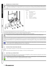
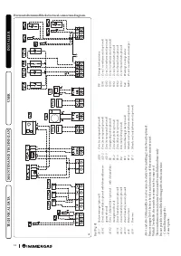
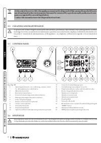
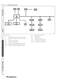
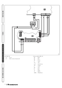
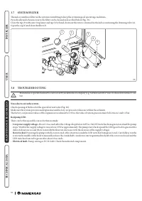
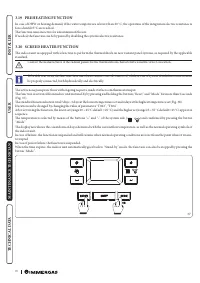
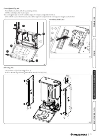
Connection cables must respect the prearranged routes.
Use 3 clips (c) (not supplied) to group the individual cables (max. 1.5 mm
2
into the lower terminal board.
Use the specific fairleads (d) on the left side, making sure to put at most 2 multi-polar cables (max 3 x 1 mm
2
) in each fairlead.
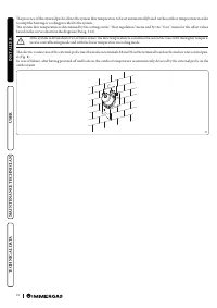
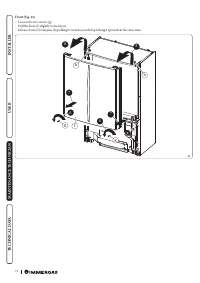
The figure 6 shows cables in a hypothetical connection. To make the connections based on your own requirements, see the instructions
below.
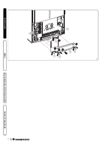
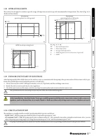
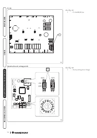
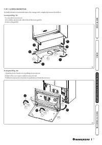
Open the control panel connections compartment
Fig. 6.
To carry out electrical connections, all you have to do is open the connections compartment as follows.
1. Remove the front panel.
2. Disassemble the cover.
3. Loosen the screws (a).
4. Remove the cover (b) from the control panel (c).
At this point, you can access the terminal board.
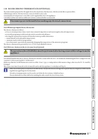
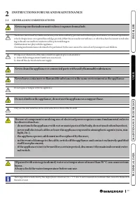
Also ensure that the electrical installation corresponds to maximum absorbed power specifications as shown on the indoor unit da-
ta-plate.
Indoor units are supplied complete with an “X” type power cable without plug.
The power supply cable must be connected to a 230V ±10% / 50Hz mains supply respecting L-N
polarity and earth connection; this network must also have a multi-pole circuit breaker with
class III overvoltage category in compliance with installation regulations.
To protect from possible dispersions of DC voltage, it is necessary to provide a type A differen-
tial safety device.
If the power supply cable is damaged, it must be replaced by a special cable or assembly, which
are only available from the manufacturer or its Authorised After-Sales Technical Assistance
Centre.
It is recommended to contact a qualified company (e.g. the Authorised After-Sales Technical
Assistance Centre) for replacement to avoid a hazard.
The power cable must be laid as shown (Fig. 6).
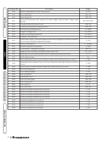
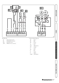
If the fuses on the circuit boards need to be replaced, this must also be done by qualified personnel: use a F3.15A H250V fuse on the P.C.B.
For the main power supply to the appliance, never use adapters, multiple sockets or extension leads.
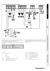
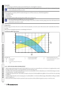
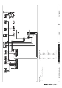
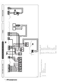
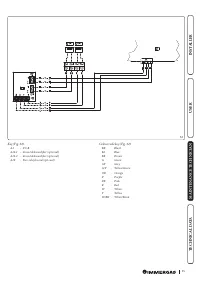
Make the various electrical connections according to your needs (Fig. 7, 8):
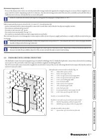
Outdoor unit electrical connection
The indoor unit must be coupled to an outdoor unit by connecting terminals F1 and F2 as shown in the wiring diagram (Fig. 8). The in-
door unit is powered at 230 V, regardless of the outdoor unit.
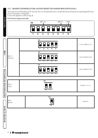
Configure the indoor unit parameters as indicated in paragraph (Parag. 3.9).
Photovoltaic system installation
Connecting the product to a photovoltaic system enhances use of the outdoor unit when the photovoltaic panels are operating. Carry out
the connection as indicated (Fig. 7).
Dehumidifiers
Carry out the connection as indicated (Fig. 8). To complete the connection operations, insert the 2-relay Board optional kit.
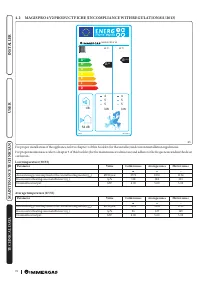
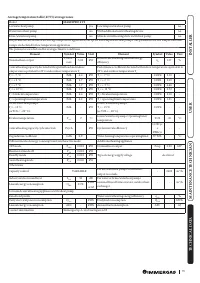
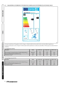
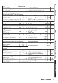
Характеристики

Остались вопросы?Не нашли свой ответ в руководстве или возникли другие проблемы? Задайте свой вопрос в форме ниже с подробным описанием вашей ситуации, чтобы другие люди и специалисты смогли дать на него ответ. Если вы знаете как решить проблему другого человека, пожалуйста, подскажите ему :)


