
Дрели Bosch GBM 1600 RE - инструкция пользователя по применению, эксплуатации и установке на русском языке. Мы надеемся, она поможет вам решить возникшие у вас вопросы при эксплуатации техники.
Если остались вопросы, задайте их в комментариях после инструкции.
"Загружаем инструкцию", означает, что нужно подождать пока файл загрузится и можно будет его читать онлайн. Некоторые инструкции очень большие и время их появления зависит от вашей скорости интернета.


English |
13
Bosch Power Tools
1 609 92A 2GV | (27.7.16)
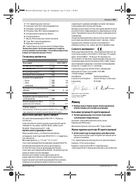
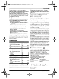
Noise/Vibration Information
Sound emission values determined according to
EN 60745-2-1.
Typically the A-weighted noise levels of the product are:
Sound pressure level 85 dB(A); Sound power level 96 dB(A).
Uncertainty K = 3 dB.
Wear hearing protection!
Vibration total values a
h
(triax vector sum) and uncertainty K
determined according to EN 60745-2-1:
Drilling into metal: a
h
< 2.5 m/s
2
, K = 1.5 m/s
2
.
The vibration level given in this information sheet has been
measured in accordance with a standardised test given in
EN 60745 and may be used to compare one tool with anoth-
er. It may be used for a preliminary assessment of exposure.
The declared vibration emission level represents the main ap-
plications of the tool. However if the tool is used for different
applications, with different accessories or insertion tools or is
poorly maintained, the vibration emission may differ. This
may significantly increase the exposure level over the total
working period.
An estimation of the level of exposure to vibration should also
take into account the times when the tool is switched off or
when it is running but not actually doing the job. This may sig-
nificantly reduce the exposure level over the total working
period.
Identify additional safety measures to protect the operator
from the effects of vibration such as: maintain the tool and the
accessories, keep the hands warm, organisation of work pat-
terns.
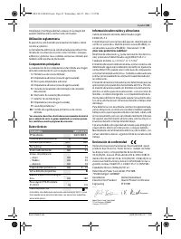
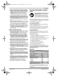
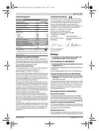
Declaration of Conformity
We declare under our sole responsibility that the product de-
scribed under “Technical Data” is in conformity with all rele-
vant provisions of the directives 2011/65/EU, until
19 April 2016: 2004/108/EC, from 20 April 2016 on:
2014/30/EU, 2006/42/EC including their amendments and
complies with the following standards: EN 60745-1,
EN 60745-2-1, EN 50581.
Technical file (2006/42/EC) at:
Robert Bosch Power Tools GmbH, PT/ETM9,
70538 Stuttgart, GERMANY
Robert Bosch Power Tools GmbH
70538 Stuttgart, GERMANY
Stuttgart, 01.01.2017
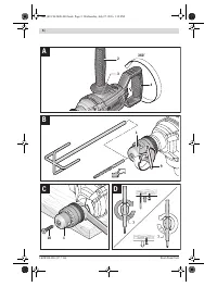
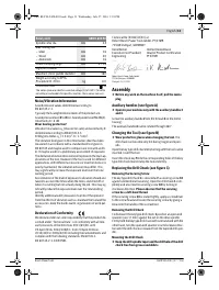
Assembly
Before any work on the machine itself, pull the mains
plug.
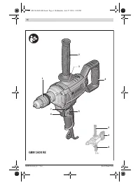
Auxiliary handles (see figure A)
Operate your machine only with the auxiliary handles 2
and 4.
Screw the auxiliary handle
2
into the thread
3
on the motor
housing.
The auxiliary handle
4
can be rotated through 360 °.
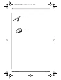
Changing the Tool (see figure B)
Wear protective gloves when changing the tool.
The
drill chuck can become very hot during longer work peri-
ods.
Open the key type drill chuck
1
by turning until the tool can be
inserted. Insert the tool.
Insert the chuck key
9
into the corresponding holes of the key
type drill chuck
1
and clamp the tool uniformly.
Replacing the Drill Chuck (see figure C)
Removing the Securing Screw
The key type drill chuck
1
is secured with a securing screw
10
against unintentional loosening. Open the drill chuck
1
com-
pletely and unscrew the securing screw
10
by turning in
clockwise direction.
Please observe that the securing
screw has a left-hand thread.
If the securing screw
10
is seated tightly, apply a screwdriver
to the screw head and loosen the securing screw by giving a
blow onto the handle of the screwdriver.
Removing the Drill Chuck
To dismount the key type drill chuck
1
position an open-end
spanner (size 17 mm) against the nut on the drive spindle.
Firmly hold the key type drill chuck with one hand and with the
other hand, turn the open-end spanner in anticlockwise direc-
tion until the drill chuck is released from the tapered drill spin-
dle.
Mounting the Drill Chuck
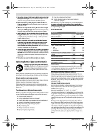
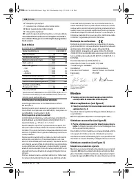
Keep the drill spindle taper and the drill hole of the drill
chuck free from grease and debris.
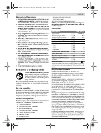
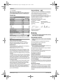
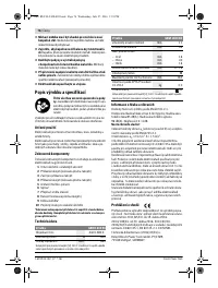
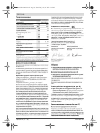
Spindle collar dia.
mm
43
Max. drilling dia.
– Steel
– Wood
– Aluminium
mm
mm
mm
16
40
16
Chuck clamping range
mm
3 – 16
Right/left rotation
Maximum stirrer paddle diameter
mm
160
Weight according to EPTA-
Procedure 01:2014
kg
3.0
Protection class
/
II
Rotary drill
GBM 1600 RE
The values given are valid for a nominal voltage [U] of 230 V. For differ-
ent voltages and models for specific countries, these values can vary.
Henk Becker
Executive Vice President
Engineering
Helmut Heinzelmann
Head of Product Certification
PT/ETM9
OBJ_BUCH-2420-003.book Page 13 Wednesday, July 27, 2016 1:18 PM
Содержание
- 90 Указания по технике безопасности для дрелей
- 91 Дополнительные предупредительные; Описание продукта и услуг; Применение по назначению
- 92 Технические данные; Заявление о соответствии; Сборка
- 93 Отсос пыли и стружки; Работа с инструментом; Включение электроинструмента
- 94 Техобслуживание и сервис; Техобслуживание и очистка; Утилизация
Характеристики

Остались вопросы?Не нашли свой ответ в руководстве или возникли другие проблемы? Задайте свой вопрос в форме ниже с подробным описанием вашей ситуации, чтобы другие люди и специалисты смогли дать на него ответ. Если вы знаете как решить проблему другого человека, пожалуйста, подскажите ему :)


