
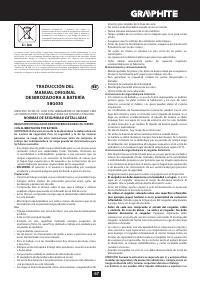
Триммеры GRAPHITE Energy+ 18 В без АКБ 58G030 - инструкция пользователя по применению, эксплуатации и установке на русском языке. Мы надеемся, она поможет вам решить возникшие у вас вопросы при эксплуатации техники.
Если остались вопросы, задайте их в комментариях после инструкции.
"Загружаем инструкцию", означает, что нужно подождать пока файл загрузится и можно будет его читать онлайн. Некоторые инструкции очень большие и время их появления зависит от вашей скорости интернета.


11
CONSTRUCTION AND USE
Cordless grass trimmer is a battery-powered tool. The drive consists of
DC commutator motor with permanent magnets. Tool of this type is
designed for tasks in home garden. The grass trimmer is designed for
trimming grass in corners and edges of lawns and flowerbeds, wherever
lawn mower cannot reach.
Use the power tool in accordance with the manufacturer’s
instructions only.
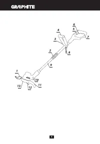
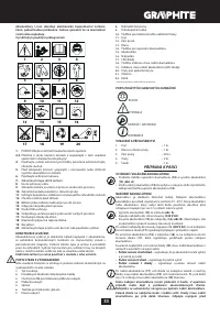
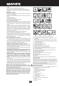
DESCRIPTION OF DRAWING PAGES
Below enumeration refers to the device elements depicted on the
drawing pages of this manual.
1.
Edge rod
2.
Locking ring for telescopic pipe
3.
Locking knob for auxiliary handle
4.
Auxiliary handle
5.
Switch
6.
Switch lock button
7.
Main handle
8.
Spare cutting parts
9.
Telescopic pipe
10.
Locking button for head tilt angle
11.
Guard
12.
Cutting part
13.
Head
14.
Battery lock button
15.
Battery
16.
Charger
17.
LED diodes
18.
Button for battery level indication
19.
Battery level indicator (LED)
20.
Guard attachment screws
21.
Spindle
22.
Pin
* Differences may appear between the product and drawing.
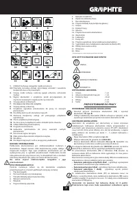
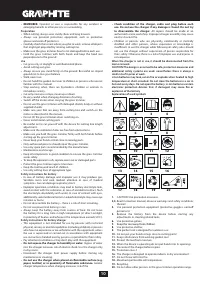
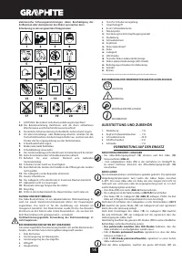
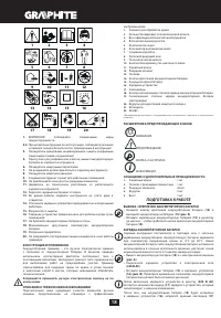
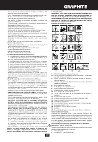
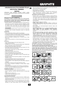
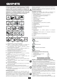
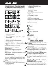
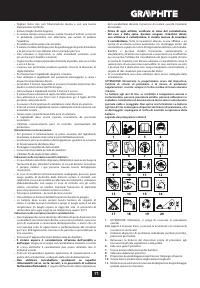
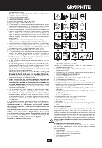
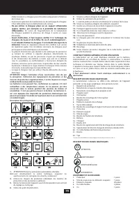
MEANING OF SYMBOLS
CAUTION
WARNING
ASSEMBLY / SETTINGS
INFORMATION
EQUIPMENT AND ACCESSORIES
1.
Guard
-
1
pce
2.
Head with cutting parts
- 1 pce
3.
Cutting
parts
-
20
pcs
4.
Screws
-
2
pcs
5.
Screw
-
1
pce
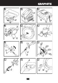
PREPARATION FOR OPERATION
REMOVING AND INSERTING THE BATTERY
•
Push the battery lock button (
14
) and slide out the battery (
15
) (
fig.
A
).
•
Insert charged battery (
15
) into the handle holder, you should hear
when the battery lock button (
14
)
snaps.
BATTERY CHARGING
The battery for the device is supplied partially charged. Charge the
battery in ambient temperature between 4°C and 40°C. New battery, or
one that has not been used for a long time, will reach full efficiency after
approximately 3 to 5 charge/discharge cycles.
•
Remove the battery (
15
) from the device (
fig. A
).
•
Connect the charger to mains socket (
230 V AC
).
•
Slide the battery (
15
) into the charger (
16
) (
fig. B
). Make sure the
battery is properly fitted (pushed to the end).
When the charger is connected to a mains socket (
230 V AC
), the green
diode (
17
) on the charger turns on to indicate connected supply.
When the battery (
15
) is placed in the charger (
16
), the red diode (
17
)
on the charger turns on to indicate that the charging is in progress.
At the same time green diodes (
19
) of the battery level indication are
flashing in different configurations, see description below.
• All diodes are flashing
– the battery is empty and requires charging.
• 2 diodes are flashing
– the battery is partially discharged.
• 1 diode is flashing
– the battery level is high.
Once the battery is charged, the diode (
17
) on the charger lights green,
and all battery level diodes (
19
) light continuously. After some time
(approx. 15 s) the battery level indication diodes (
19
) turn off.
Do not charge the battery for more than 8 hours. Exceeding this time
limit may cause damage to battery cells. The charger does not turn
off automatically when the battery is full. Green diode on the charger
will remain on. Battery level indication diodes turn off after some
time. Disconnect power supply before removing the battery from the
charger socket. Avoid consecutive short chargings. Do not charge the
battery after short use of the tool. Significant decrease of the period
between chargings indicates the battery is worn out and should be
replaced.
Batteries heat up when charging. Do not operate just after charging –
wait for the battery to cool down to room temperature. It will prevent
battery damage.
BATTERY LEVEL INDICATION
The battery is equipped with signalisation of the battery level (3 LED
diodes) (
19
). To check battery level status, press the button for battery
level indication (
18
) (
fig. C
). When all diodes are lit, the battery level is
high. When 2 diodes are on, the battery is partially discharged. When
only one diode is lit, the battery is discharged and must be recharged.
GUARD INSTALLATION
•
Put the guard (
11
) on the motor casing, so the protective section is
pointed towards the operator.
•
Secure the guard (
11
) to the motor casing with the supplied screws
(
20
) (
fig. D
).
HEAD INSTALLATION
The head (
13
) is supplied disassembled with 2 attached cutting parts
(
12
).
•
Put the head (
13
) onto the spindle (
21
) so that its flat section with the
hole matches the corresponding area of the spindle (
fig. D
).
•
Use supplied screw and turn counter clockwise to tighten (left-hand
thread) (
fig. E
).
The device can operate correctly only when the head is equipped
with 2 cutting parts. Operation with only 1 cutting part is forbidden.
EDGE ROD
The edge rod is used to trim grass near edges and corners of lawns.
It protects the cutting parts from damaging with sharp edges, e.g.
concrete pavement sides.
•
The edge rod (
1
) located on the motor casing can be adjusted by
sliding it in or out, according to the needs (
fig. F
).
ADJUSTMENT OF THE AUXILIARY HANDLE
Auxiliary handle is designed for right- and left-handed persons. When
starting operation always hold the grass trimmer firmly with both hands
and by two handles.
•
Loosen the locking knob for auxiliary handle (
3
) and set the auxiliary
handle (
4
) in the optimal position for the task at hand (
fig. G
).
•
Tighten the locking knob for auxiliary handle (
3
) to secure it in the
position.
LENGTH ADJUSTMENT OF THE TELESCOPIC PIPE
Length adjustment of the telescopic pipe allows to match height of the
tool with persons with various height and posture.
•
Loosen the locking ring for telescopic pipe (
2
).
•
Slide out/in the telescopic pipe (
9
) to desired length (
fig. H
).
•
Lock by tightening the locking ring of the telescopic pipe (
2
).
SETTING TILT ANGLE OF THE MAIN HANDLE
Thanks to convenient feature of adjustable head angular position
related to the main handle, it is possible to trim lawn and flower bed
edges and mow in hard to reach areas, e.g. under seats, hammock, table
etc.
•
Press in the locking button for head tilt angle (
10
).
•
Press on the telescopic pipe (
9
) to choose desired angle of the head
tilt (
fig. I
).
•
Release the locking button for head tilt angle (
10
) to automatically
secure selected position.


