Сварочное оборудование Awelco MIG ONE - инструкция пользователя по применению, эксплуатации и установке на русском языке. Мы надеемся, она поможет вам решить возникшие у вас вопросы при эксплуатации техники.
Если остались вопросы, задайте их в комментариях после инструкции.
"Загружаем инструкцию", означает, что нужно подождать пока файл загрузится и можно будет его читать онлайн. Некоторые инструкции очень большие и время их появления зависит от вашей скорости интернета.

·
Very thick or wide welding
Can be caused by moving the torch too slowly.
·
Wire burns back
It can be caused by wire feed slipping, loose or damaged
welding tip, poor wire, nozzle held too close to work or
voltage too high.
· Little
penetration
It can be caused by moving torch too fast, too low voltage
setting or incorrect feed setting, reversed polarity, insufficient
blunting and distance between strips. Take care of
operational parameters adjustment and improve the
preparation of the workpieces.
· Workpiece’s
piercing
It may be caused by moving the welding torch too slow, too
high welding power or by an invalid wire feeding.
·
Heavy spatter and porosity
It can be caused by nozzle too far from work, dirt on work or
by low gas flow. You have to the two parameters, remeber
that gas has not to be lower than 7-8 liters/ min. and that the
current of welding is appropriated to the wire you are using. It
is advisable to have a pressure reducer of input and output.
On the manometer you can read the range expressed in liter.
·
Welding arc instability
It may be caused by an insufficient welding voltage, irregular
wire feed, insufficient protective welding gas.
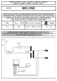
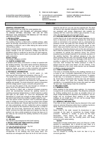
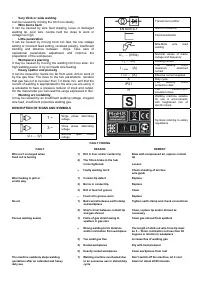
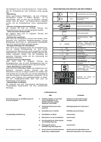
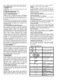
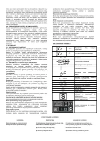
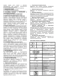
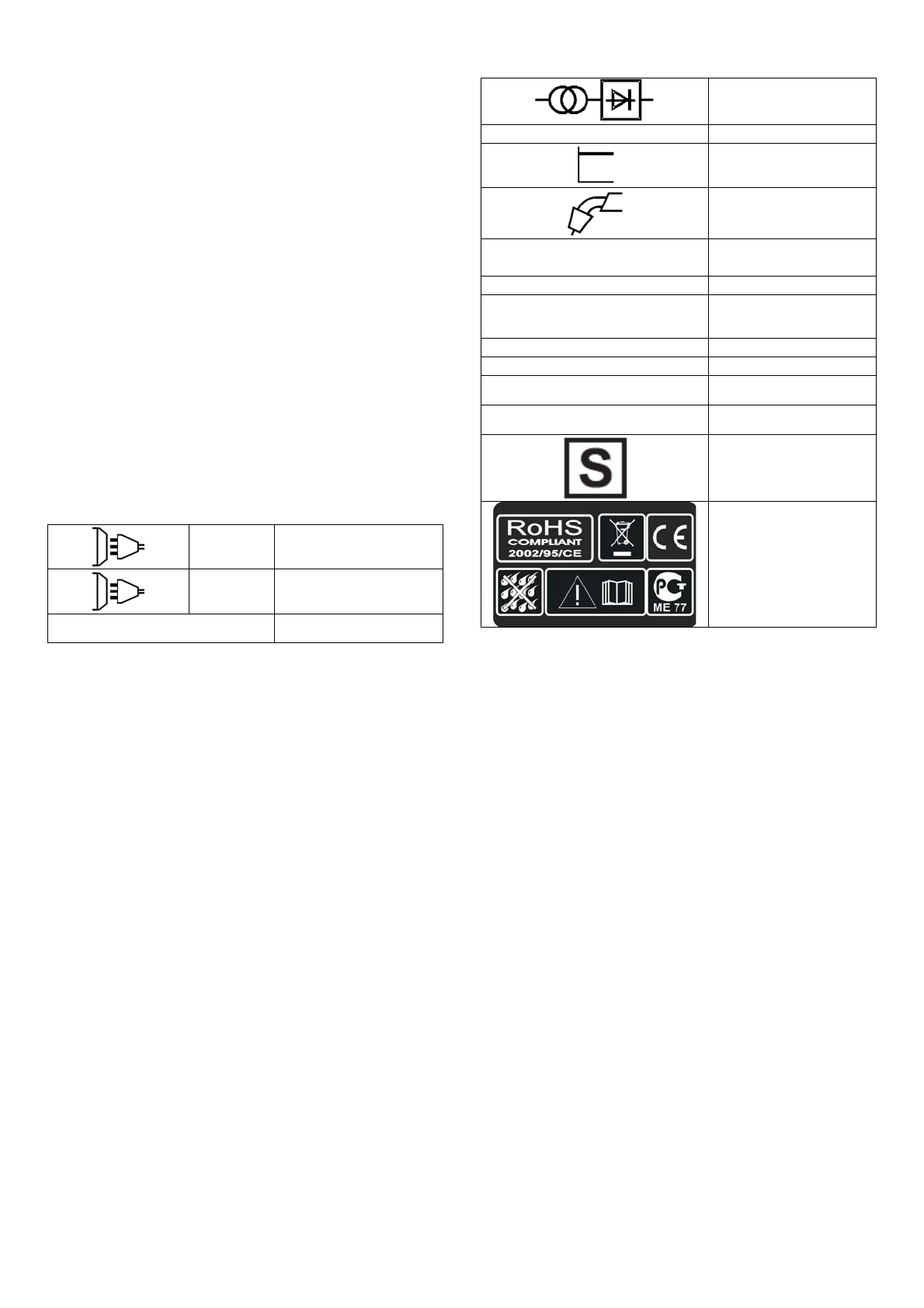
DESCRIPTION OF SIGNS AND SYMBOLS
1 ~
Single phase alternating
voltage
3 ~
Three phase alternating
voltage
U
0
… (V)
Nominal open circuit
voltage
Transformer-rectifier
EN 60974-1
Norm of reference
Flat characteristic
MIG-MAG wire feed
welding
U
1
… (V/Hz)
Nominal values of mains
voltage and frequency
I
2
… (A)
Welding current
I
1 max
(A)
The welding unit's
maximum absorbed
current
I
1 eff
… (A)
Effective current supplied
X
Duty cycle
IP21
The welding unit's
protection class
H
The transformer's
insulation class.
Welding machine suitable
for use in environments
with heightened risk of
electric shock.
Symbols referring to safety
regulations
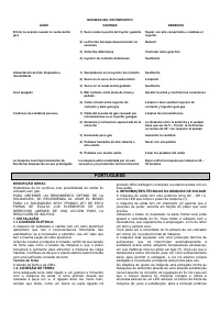
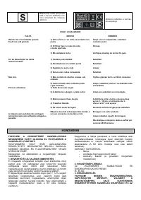
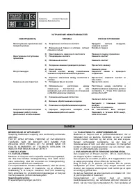
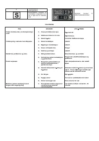
FAULT FINDING
FAULT
Wire isn’t conveyed when
Feed roll is turning
Wire feeding in jerk or
erratic way
No arc
Porous welding seams
The machine suddenly stops welding
operations after an extended and heavy
duty use
REASON
1) Dirt in liner and/or contact tip
2) The frition brake in the hub
is too tightened
3)
Faulty welding torch
1) Contact tip defect
2) Burns in contact tip
3) Dirt in feed roll groove
4)
Feed roll’s groove worn
1) Bad concat between earth clamp
and workpiece
2) Short-circuit between contact tip
and gas shroud
1) Failre of gas shield owing to
spatters in gas shro
2)
Wrong welding torch distance
and/or inclination from workpiece
3) Too small gas flux
4) Humid
workpieces
5) Heavily
rusted
workpieces
1) Welding machine overheated due
to an excessive use in stated duty
cycle
REMEDY
Blow with compressed air, replace contact
tip
Loosen
Check sheating of torchès
wire guide
Replace
Replace
Clean
Replace
Tighten earth clamp and check connections
Clean, replace tip and/or shroud as
necessary
Clean gas shroud from spatters
The length of stick out wire from tip must
be 5 – 10mm. Inclination not less than 60
degrees in relation to woekpiece
Increase flux of welding gas
Dry with heat producer
Clean workpieces from rust
Don’t switch off the machine, let it cool
down for about 20/30 minutes

